Atec Agilent-346a User Manual
Page 39
39
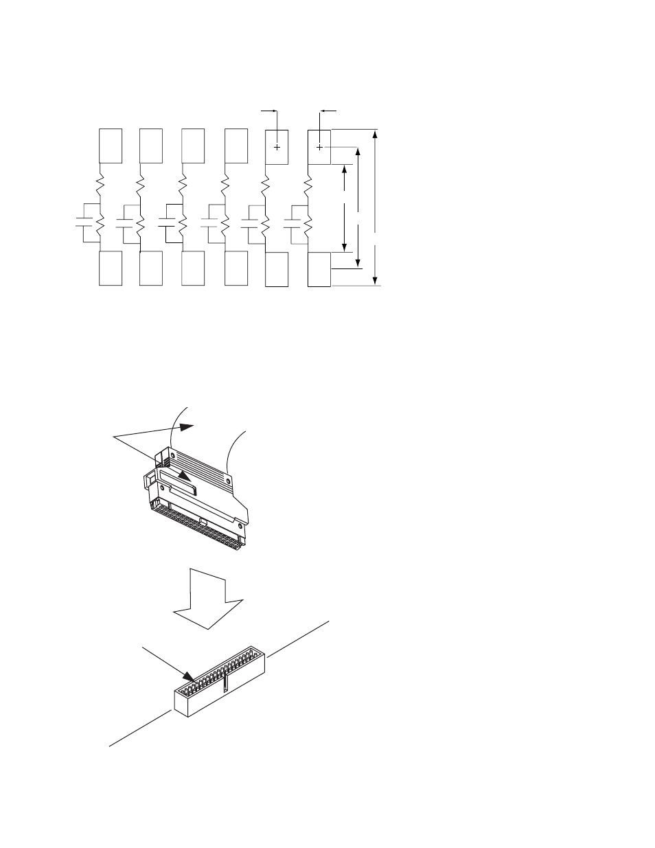
Designing and Probing with Target Connections
For All Agilent Logic Analyzers with 40-pin Pod Connectors
Figure 7.8. Connecting probe cable to 40-pin connector with isolation networks
Probe cable
(from logic
analyzer)
40-pin connector
(Agilent part number 1251-8828C)
2 x 20-pin male connector with
0.1” x 0.1” spacing
Logic Analyzer Pod
Pad Dimension = 0.030” x 0.040”
7
5
8
9
10
3
11
2
1
12
0.050”
0.080”
0.120”
0.160”
R1
C1
R2
R3
R4
R5
R6
R7
C2
R8
C3
R9
C4
R10
C5
R11
C6
R12
Notes:
4
6
1. Resistances:
R1 through R6: 250
Ω
R7 through R12: 90.9 k
Ω
2. Capacitance 8.2 pF
Figure 7.7. Recommended PC board pattern for 5062-7396 surface mount isolation network
See also other documents in the category Atec Equipment:
- Anritsu-PIM-MW82119A (2 pages)
- Boonton-PIM31 (6 pages)
- AWT-PIM-S1L-Tetra Series (2 pages)
- AWT-PIM-S1P Series (2 pages)
- AWT-PIM-S1L Series (2 pages)
- AWT-PIM-Expandable Series (2 pages)
- AWT-PIM-Single Series (2 pages)
- CCI-PimPro (4 pages)
- JDSU-FST-2310 (10 pages)
- JDSU-T-Berd-6000 (8 pages)
- Agilent-N9912A (2 pages)
- Agilent-E5515C (4 pages)
- Agilent-E4406A (20 pages)
- Agilent-N4010A (16 pages)
- Anritsu-S412E (19 pages)
- Anritsu-S810D-S820D (2 pages)
- Anritsu-S820E (16 pages)
- Anritsu-MT8221B (24 pages)
- Anritsu-MT8221B (28 pages)
- Anritsu-S412D (16 pages)
- Anritsu-MT8222A (8 pages)
- Anritsu-MT8220T (28 pages)
- Anritsu-MT8212E-MT8213E (32 pages)
- Anritsu-S332D-31D (12 pages)
- Anritsu-MT8212A (2 pages)
- Bird-SA Series (2 pages)
- Anritsu-S331E-S332E-S361E-S362E (16 pages)
- Anritsu-S331L (12 pages)
- Advantest-Q8163 (1 page)
- Agilent-83557A-83558A (4 pages)
- Agilent-8169A (6 pages)
- Agilent-11896A (5 pages)
- Agilent-81689A_B-81649A (6 pages)
- Agilent-8163A-81634A (8 pages)
- Agilent-81624B (11 pages)
- Agilent-81618A (112 pages)
- Agilent-8703A (16 pages)
- Agilent-8156A (8 pages)
- Advanced-Fiber-Solutions-OLK51 Series (5 pages)
- Anritsu_MS9720A (12 pages)
- Anritsu-ML9001A (4 pages)
- Corning-Optivisor400 (6 pages)
- Anritsu_CMA5000a (4 pages)
- Agilent-E6008B (12 pages)
- AFL-Noyes-FLX3 (6 pages)