Atec Agilent-346a User Manual
Page 14
14
General-Purpose Probing
For All Agilent Logic Analyzers with 40-pin Pod Connectors
Signal Line Loading
Any probed signal line must be
able to supply a minimum of
600 mV (unless noted otherwise —
see probe of interest) to the probe
tip while the probe is connected
to the system. The maximum
input voltage of each probe is
±40 volts peak (unless noted oth-
erwise — see probe of interest).
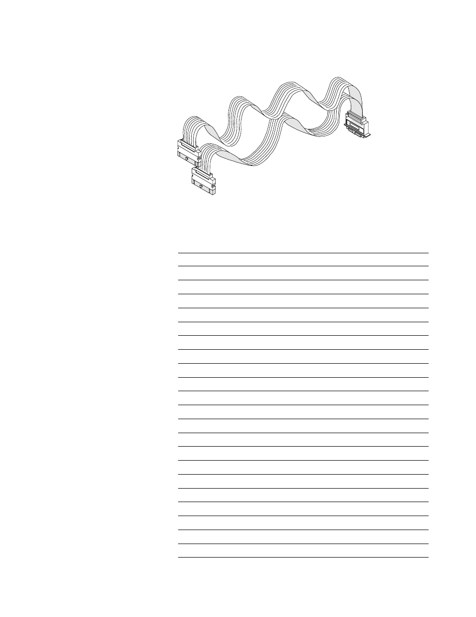
Probe Cables
The probe cable (see Figure 4.7
and Table 4) contains 16 signal
lines and two clk lines, two +5 volt
power lines, and ground lines
for each of the signal/clock and
power lines. All of these lines are
contained in a 4.5-foot cable. The
probe cable is included with the
logic analyzer. The cable grounds
are chassis (earth) grounds, not
“floating” grounds. The two
+5 volt power lines can be used
to power active probing systems.
Consult the specifications for the
individual logic analyzers or logic
analyzer cards for the maximum
allowable current through each
+5 volt power supply.
Caution: These +5 volt power
lines MUST NOT be connected to
the target’s power supply.
Caution: Be careful when using
straight wire probe leads, one
common ground, or RC networks
located far from the target.
These circumstances increase
the impact of analog effects
such as crosstalk and EMT
susceptibility, which contribute
to measurement errors.
Logic Analyzer
01660-61605
16555-61606
16710-61603
16715-61601
Stand Alone or Module
16550A
x
16554A
x
16555A/D
x
16556A/D
x
16557D
x
16710A
x
16711A
x
16712A
x
16715A
x
16716A
x
16717A
x
16718A
x
16719A
x
16740 Series
x
16750A/B
x
16751A/B
x
16752A/B
x
16910A
x
16911A
x
1670 Series
x
1680 Series
x
1690 Series
x
Table 4. Probe cables supplied with Agilent logic analyzers
Figure 4.7. Logic analyzer probe cable