Atec Agilent-346a User Manual
Page 33
33
Designing and Probing with Target Connections
For All Agilent Logic Analyzers with 40-pin Pod Connectors
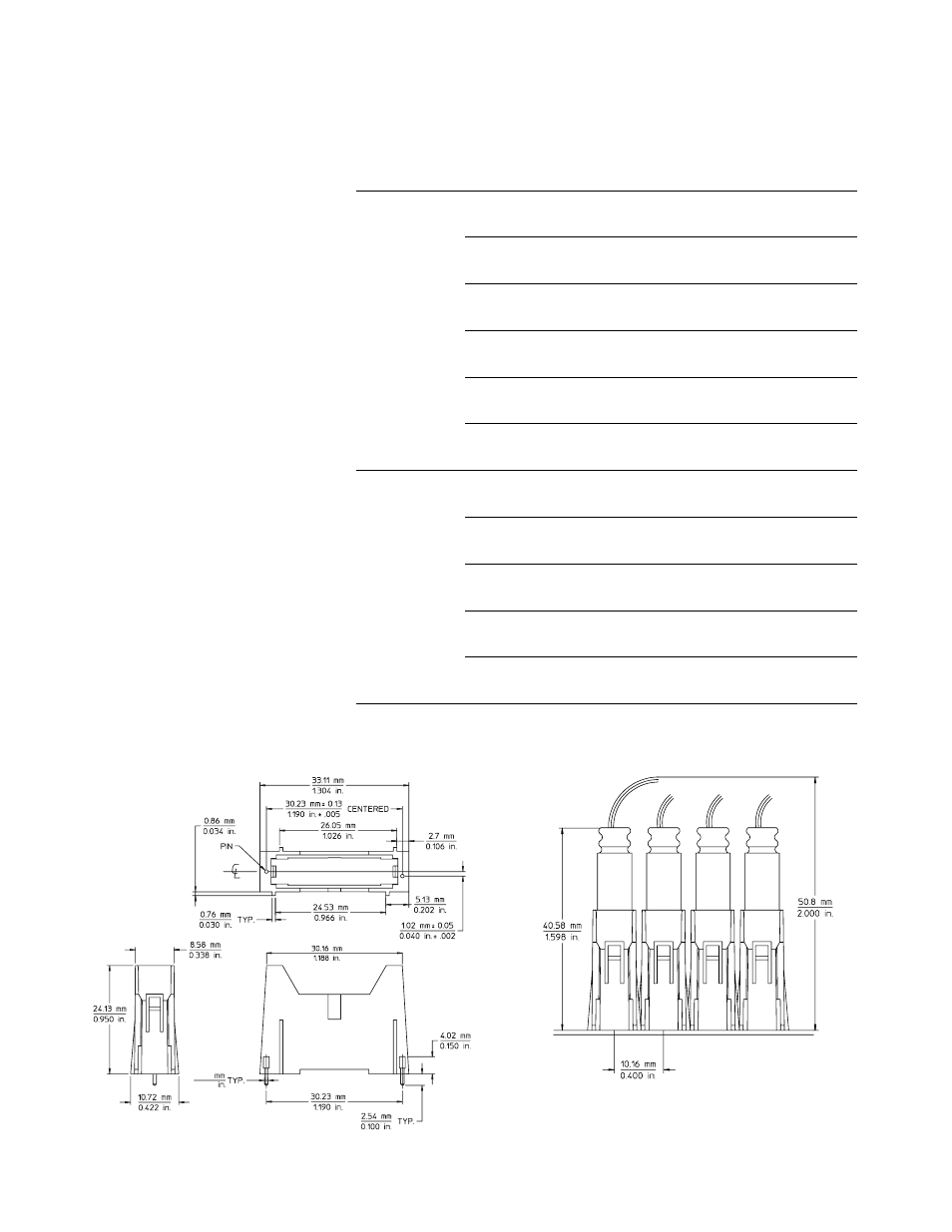
Support Shrouds
A support shroud is recom-
mended to provide additional
strain relief between the probe
and the connector, as shown in
Figures 5.21 and 5.23. Two plated
through-holes are required on the
target board. The shroud is
mounted directly to the target
board using the through-holes.
This places the shroud around
the connector, providing solid
mechanical strain relief.
Connector kits are available;
Table 5 shows the Agilent part
numbers for shrouds and
connector kits for various PC
board thicknesses.
0.64
0.025
Figure 5.27. Mechanical information for E5346-44701, E5346-44703,
E5346-44704 support shrouds for 38-pin Mictor connectors
For probe
Agilent
model numbers
Description
part number
E5339A, E5346A,
Kit of five support shrouds and five 38-pin Mictor
E5346-68701
E5351A
connectors for PC board thickness up to 1.57 mm (0.062")
Kit of five support shrouds and five 38-pin Mictor
E5346-68700
connectors for PC board thickness up to 3.175 mm (0.125")
One 38-pin Mictor connector
1252-7431
(also available from AMP as part number 2-767004-2)
One support shroud for
E5346-44701
PC board thickness up to 1.57 mm (0.062")
One support shroud for
E5346-44704
PC board thickness up to 3.175 mm (0.125")
One support shroud for
E5346-44703
PC board thickness up to 4.318 mm (0.700")
E5385A
Kit of five support shrouds and five 100-pin Samtec
16760-68702
connectors for PC board thickness up to 1.57 mm (0.062")
Kit of five support shrouds and five 100-pin Samtec
16760-68703
connectors for PC board thickness up to 3.05 mm (0.120")
One 100-pin Samtec connector
1253-3620
(also available from Samtec as part number ASP-65067-01)
One support shroud for
16760-02302
PC board thickness up to 1.57 mm (0.062")
One support shroud for
16760-02303
PC board thickness up to 3.05 mm (0.120")
Table 5. Mating connectors, shrouds, and kits for Agilent E5339A, E5346A, E5351A, and
E5385A probes