Atec Agilent-346a User Manual
Page 28
28
Designing and Probing with Target Connections
For All Agilent Logic Analyzers with 40-pin Pod Connectors
Agilent Technologies E5346A,
E5339A, and E5385A Probes
The E5346A, E5339A, and
E5385A probes include the
required isolation networks for
the logic analyzer right at the
probe tip, close to the target.
The E5346A and E5385A are
designed to acquire signals with
peak-to-peak amplitude as low as
500 mV. The E5339A is designed
to acquire signals as small as
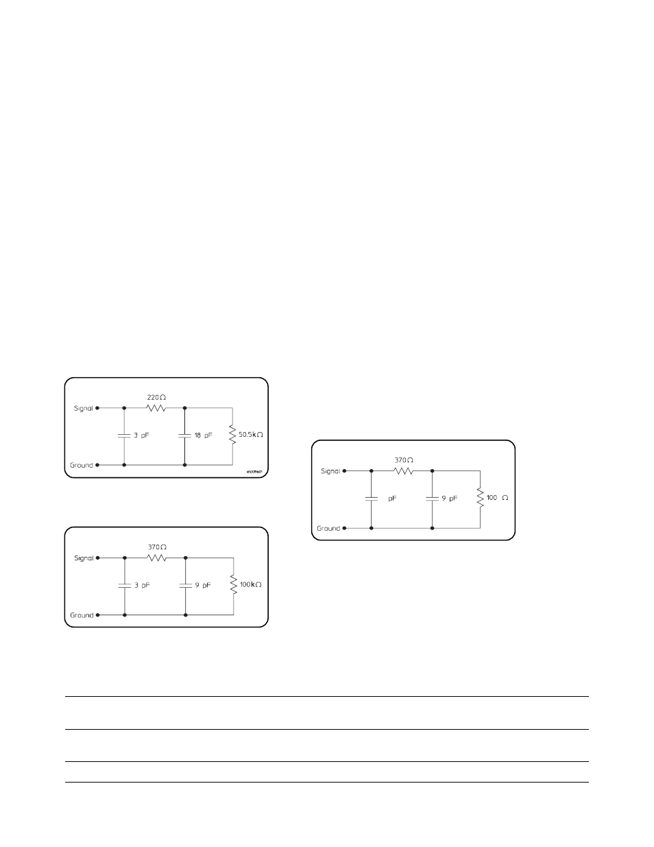
250 mV peak-to-peak. Figure 5.18
shows the equivalent load for the
E5339A, and Figure 5.19 shows
the equivalent load for the
E5346A. Figure 5.20 shows the
equivalent load for the E5385A.
To use the E5346A, E5339A, or
E5385A at high clock speeds, the
following design guidelines
should be observed:
• Calculate the electrical length
of the probe hookup stub.
• For PC board material with
E
r
=4.9, use a propagation delay
of 160 ps/inch.
• Check that the propagation
delay of the probe hookup stub
is less than 20% of the bus sig-
nal risetime (T
r
). If it is, the
E5346A, E5339A, or E5385A
can be used for connection.
For example, if E
r
=4.9, a 2.5 inch
probe hookup stub generates a
propagation delay of 400 ps.
If T
r
is > 2 ns, the E5346A,
E5339A, or E5385A is a viable
probing choice.
The E5346A and E5339A use the
AMP Mictor 38-pin connector.
The E5385A uses a 100-pin
connector manufactured by
Samtec. Agilent recommends
the E5394A or E5385A for new
applications, due to the reduced
input capacitive loading and
improved isolation between
adjacent channels.
For additional information on designing connectors into a target system, refer to the following documents:
Agilent Technologies E5346A/E5351A
Installation Note E5346-92014
http://literature.agilent.com/litweb/pdf/E5346-92014.pdf
Probe/Adapter Cable
Agilent Technologies E5339A
Installation Note E5339-92002
http://literature.agilent.com/litweb/pdf/E5339-92002.pdf
Low Voltage Probe
Agilent Technologies E5385A Probe
Installation Note E5385-92001
http://literature.agilent.com/litweb/pdf/E5385-92001.pdf
Figure 5.19. E5346A input equivalent load
Figure 5.18. E5339A input equivalent load
Equivalent Load
Equivalent Load
k
1.5
Figure 5.20. E5385A input equivalent load
Equivalent Load