Atec Agilent-346a User Manual
Page 37
37
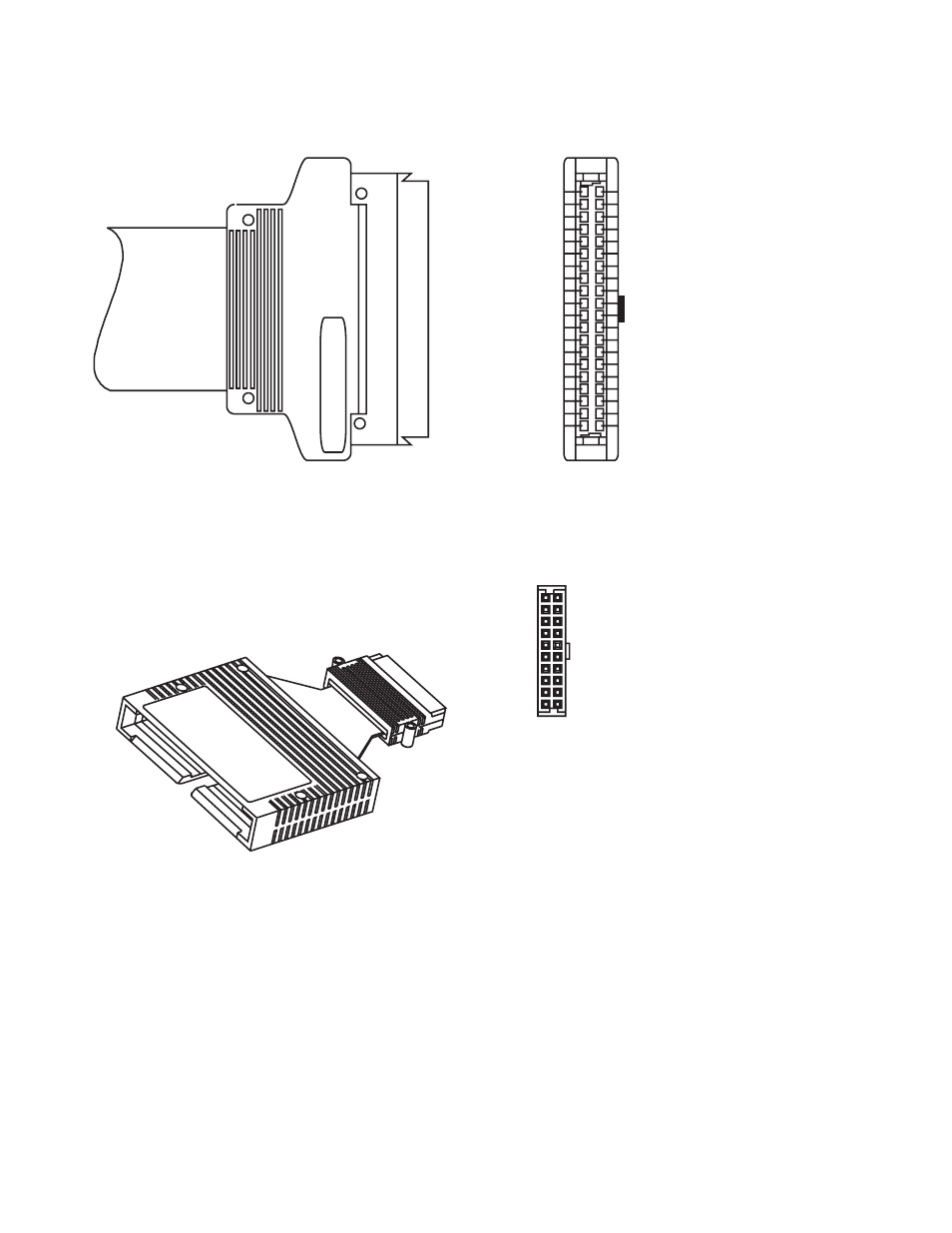
Designing and Probing with Target Connections
For All Agilent Logic Analyzers with 40-pin Pod Connectors
SIGNAL GND 4
SIGNAL GND 6
SIGNAL GND 8
SIGNAL GND 10
POWER GND 2
SIGNAL GND 12
SIGNAL GND 14
SIGNAL GND 16
SIGNAL GND 18
SIGNAL GND 20
SIGNAL GND 22
SIGNAL GND 24
SIGNAL GND 26
SIGNAL GND 28
SIGNAL GND 30
SIGNAL GND 32
SIGNAL GND 34
SIGNAL GND 36
SIGNAL GND 38
POWER GND 40
1 +5V (see note)
3 CLOCK
5 Do not connect
7 D15
9 D14
11 D13
13 D12
15 D11
17 D10
19 D9
21 D8
23 D7
25 D6
27 D5
29 D4
31 D3
33 D2
35 D1
37 D0
39 +5V
1 +5V (see note)
3 CLOCK
5 D14
7 D12
9 D10
11 D8
13 D6
15 D4
17 D2
19 D0
Do not connect 2
D15 4
D13 6
D11 8
D9 10
D7 12
D5 14
D3 16
D1 18
GND 20
Figure 7.5. Pinout for 100 k
Ω isolation adapter (Agilent part number 01650-63203)
Figure 7.4. Pinout for probe cable
Note: +5V is supplied from the
logic analyzer to provide power
for analysis probes and demo
boards. DO NOT connect these
pins to a +5V supply in the
target system!
- Anritsu-PIM-MW82119A (2 pages)
- Boonton-PIM31 (6 pages)
- AWT-PIM-S1L-Tetra Series (2 pages)
- AWT-PIM-S1P Series (2 pages)
- AWT-PIM-S1L Series (2 pages)
- AWT-PIM-Expandable Series (2 pages)
- AWT-PIM-Single Series (2 pages)
- CCI-PimPro (4 pages)
- JDSU-FST-2310 (10 pages)
- JDSU-T-Berd-6000 (8 pages)
- Agilent-N9912A (2 pages)
- Agilent-E5515C (4 pages)
- Agilent-E4406A (20 pages)
- Agilent-N4010A (16 pages)
- Anritsu-S412E (19 pages)
- Anritsu-S810D-S820D (2 pages)
- Anritsu-S820E (16 pages)
- Anritsu-MT8221B (24 pages)
- Anritsu-MT8221B (28 pages)
- Anritsu-S412D (16 pages)
- Anritsu-MT8222A (8 pages)
- Anritsu-MT8220T (28 pages)
- Anritsu-MT8212E-MT8213E (32 pages)
- Anritsu-S332D-31D (12 pages)
- Anritsu-MT8212A (2 pages)
- Bird-SA Series (2 pages)
- Anritsu-S331E-S332E-S361E-S362E (16 pages)
- Anritsu-S331L (12 pages)
- Advantest-Q8163 (1 page)
- Agilent-83557A-83558A (4 pages)
- Agilent-8169A (6 pages)
- Agilent-11896A (5 pages)
- Agilent-81689A_B-81649A (6 pages)
- Agilent-8163A-81634A (8 pages)
- Agilent-81624B (11 pages)
- Agilent-81618A (112 pages)
- Agilent-8703A (16 pages)
- Agilent-8156A (8 pages)
- Advanced-Fiber-Solutions-OLK51 Series (5 pages)
- Anritsu_MS9720A (12 pages)
- Anritsu-ML9001A (4 pages)
- Corning-Optivisor400 (6 pages)
- Anritsu_CMA5000a (4 pages)
- Agilent-E6008B (12 pages)
- AFL-Noyes-FLX3 (6 pages)