Atec Agilent-346a User Manual
Page 55
55
Designing and Probing with Target Connections
Agilent Logic Analyzers with 90-pin Pod Connectors
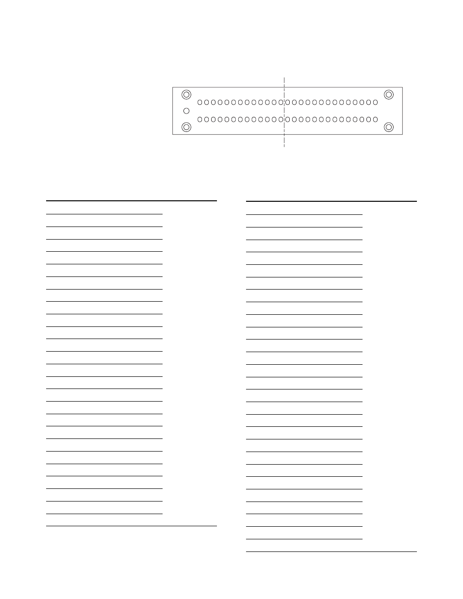
Pinout for the E5390A Single-Ended
Soft Touch Probe
The following graphic and table
show the E5390A single-ended
soft touch probe pad numbers
and logic analyzer pod inputs.
POD 1
POD 2
POD 1
POD 2
D0 D2 G D4 D6 G D8 D10 G D12 D14 G CLK G D0 D2 G D4 D6 G D8 D10 G D12 D14 G CLK
D1 D3 G D5 D7 G D9 D11 G D13 D15 G nCLK G D1 D3 G D5 D7 G D9 D11 G D13 D15 G nCLK
B1
A1
B27
A27
Figure 8.16. Pinout
E5390A Single-Ended Probe
Logic Analyzer
Signal Name
Pad #
Channel
Pod
D1
A1
➞
1
Whichever pod
D3
A2
➞
3
is connected to
Ground
A3
“Odd” on the
D5
A4
➞
5
E5390A probe
D7
A5
➞
7
Ground
A6
D9
A7
➞
9
D11
A8
➞
11
Ground
A9
D13
A10
➞
13
D15
A11
➞
15
Ground
A12
Clock (–)
A13
➞
Clock
D0
B1
➞
0
D2
B2
➞
2
Ground
B3
D4
B4
➞
4
D6
B5
➞
6
Ground
B6
D8
B7
➞
8
D10
B8
➞
10
Ground
B9
D12
B10
➞
12
D14
B11
➞
14
Ground
B12
Clock (+)
B13
➞
Clock
E5390A Single-Ended Probe
Logic Analyzer
Signal Name
Pad #
Channel
Pod
Ground
A14
Whichever pod
D1
A15
➞
1
is connected to
D3
A16
➞
3
“Even” on the
Ground
A17
E5390A probe
D5
A18
➞
5
D7
A19
➞
7
Ground
A20
D9
A21
➞
9
D11
A22
➞
11
Ground
A23
D13
A24
➞
13
D15
A25
➞
15
Ground
A26
Clock (–)
A27
➞
Clock
Ground
B14
D0
B15
➞
0
D2
B16
➞
2
Ground
B17
D4
B18
➞
4
D6
B19
➞
6
Ground
B20
D8
B21
➞
8
D10
B22
➞
10
Ground
B23
D12
B24
➞
12
D14
B25
➞
14
Ground
B26
Clock (+)
B27
➞
Clock