Dh-21 – Xylem DH-21 User Manual
Page 14
2-2 Installation
DH-21
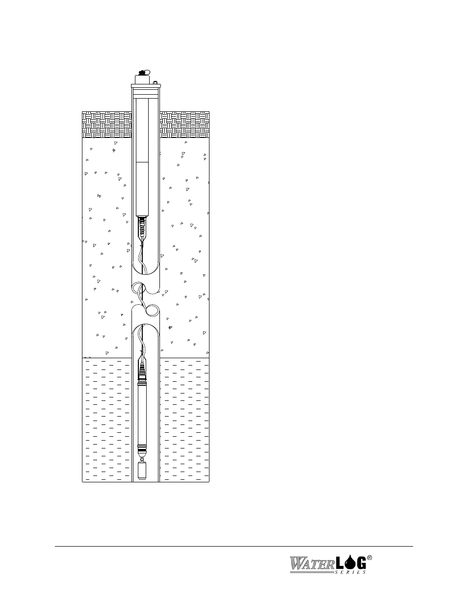
Figure 2-1.
Typical Small Bore Well Installation
2.1.2 Sample Well Installation
The “
W
ATER
LOG” can be used inside a well
casing. Figure 2-1 illustrates a typical ground
well installation. The “
W
ATER
LOG” is
suspended from the bail hook on the bottom
end of the well head assembly using the
stainless steel cable. One end of the stainless
steel cable is attached to the support bail on
the sensor and the other end is fastened to the
ring on the bottom of the battery
compartment. The ballast is attached to the
ballast hook of the sensor, as shown in Figure
2-1. The well head assembly slides through a
1-1/2" compression well cap (optional). It is
important that the well head assembly is not
submersed. There is a vent hole on the side of
the well head assembly near the top which
provides the sensor with a reference to
atmospheric pressure. The lower endcap of
the well head assembly is moisture resistant
but not watertight.
When using submersible gage pressure
transducers you must provide some means of
venting the well. The vent port of the pressure
transducer must be open to the atmosphere to
allow for proper compensation of changes in
barometric pressure. If a sanitary well seal is
used, you must drill a hole in the cap or
provide other means of venting the well. If
you purchased the well cap from Design
Analysis Associates, the vent is already
provided.