Front panel operation, View active alarms mode, 8478669412 cable set to btj2/btj3 – GE Industrial Solutions Galaxy Vector Controller GCM3 User Manual
Page 59
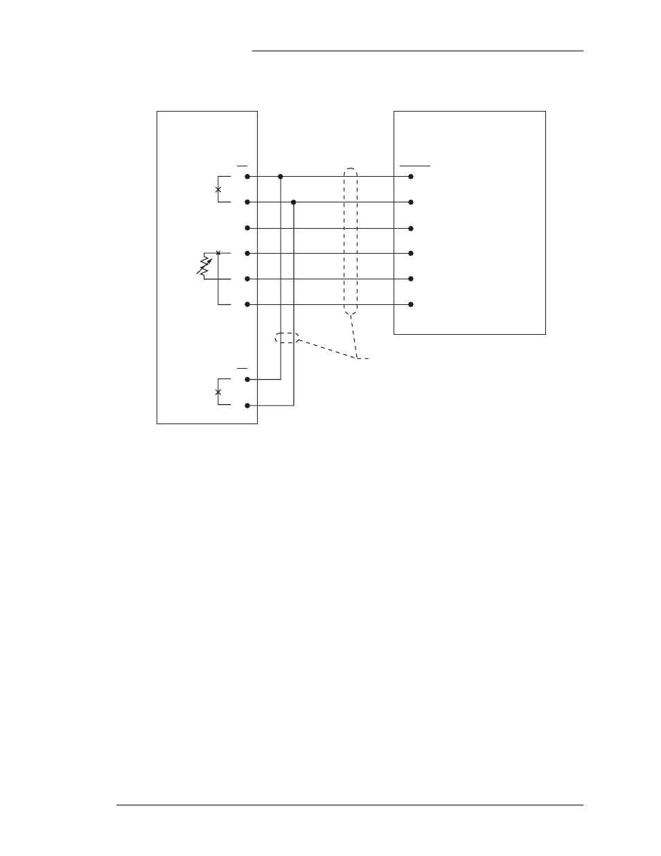
Figure 4-2b: 210E Thermistor Multiplexer Connections with 8478669412 Cable Set to BTJ2/BTJ3
210E
J4
J1
J9-J12
1
2
3
4
5
6
1
2
3
4
5
6
4
6
Temperature Alarm
Ground
Probe Signal +
Probe Signal –
Probe Present
BTJ2/3 Temperature Port
with GCM2/3 (OPS)
J9, J10, J11, J12
LED Test
848669412 Cable Set
BK
BK
O
G
G
R
Y
BR
µP Fail
Maj
Min
Ω Out
Open/Shorted
Probe
Galaxy Vector Controller GCM2, GCM3
Issue 4 January 2008
Installation and Configuration 4 - 5
Front Panel
Operation
Default Front Panel Menu
The Galaxy Vector Controller with its LCD display presents a
default front panel screen. The System Bus Voltage and Load
Current are displayed on the screen. Plant voltage is displayed
while in this mode. Regardless of the active display mode, if no
key is pressed for approximately 3 minutes, the Vector returns to
its default menu. The present operating state of the system is also
displayed on the default menu.
View Active
Alarms Mode
If alarms are active in the system, the last two rows of the screen
will provide additional softkey information. The third row will
provide a softkey that allows a user to deactivate all audible
alarms. This is performed by using the “ACO” feature. The
fourth row on the display will provide immediate access to the
system alarms. This mode is entered by pressing the View
Active Alarms softkey. While in this mode, alarms are listed in
order of severity. All major alarms will be listed first, followed
by minor alarms. If four or more alarms are present, use the up