Table 2-f: lvd drive terminals – GE Industrial Solutions Galaxy Vector Controller GCM3 User Manual
Page 23
Galaxy Vector Controller GCM2, GCM3
Issue 4 January 2008
Product Description 2 - 9
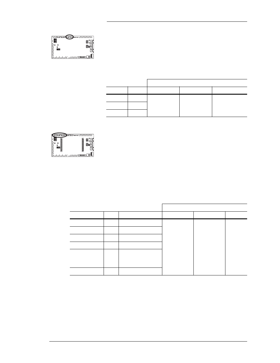
LVD1, LVD2, LVD3: Form C relay contact outputs for LVD
contactor control. These terminals are connected to BJN
contactor drive boards. LVD1 and LVD2 contacts are rated for
2 amps. LVD3 is not available in GCM controller applications.
Table 2-F shows relay state information.
Table 2-F: LVD Drive Terminals
Terminal
Contactor Relay
O
C
R
LVD1
K1
Normally open
contact
Normally closed
contact
Return (common)
LVD2
K2
LVD3
K3
Office alarm relay outputs: All alarm output relays are isolated
Form C or transfer type contacts, consisting of normally open
(NO) and normally closed (NC) contacts, with a common return
(RTN) contact. The de-energized state of these relays is the
alarm state. An alarm condition results in a closure of the
normally closed contact to the return contact, and an open
between the normally open and return contacts. Individual relay
pin descriptions are shown in Table 2-G.
Table 2-G: BLJ3 Office Alarm Relay Output Terminals
Terminal
Alarm
Relay
Alarm Description
C
O
R
PMN
K4
Power Minor
Normally open
contacts.
Closed to R
when alarm
condition exists.
Normally
closed contacts.
Open to R when
alarm condition
exists.
Return
(common)
MJF
K5
Major Fuse
BD
K6
Battery on Discharge
ACF
K7
Single AC Fail
HV/2ACF/VLV*
K8
High Voltage /
Multiple AC Fail /
Very Low Voltage
PMJ
K9
Power Major
* Relay assignment is determined by the settings of S1.2 and S1.5:
HV alarm
S1.2-0, S1.5=0
2ACF alarm S1.2=1, S1.5=0
VLV alarm
S1.2=0, S1.5=1
Setting both switches to 1 results in activating HV. The S1.2 setting is only read during GCM power up.