Gcm2 or gcm3 control board, User interface control panel, Figure 2-3: galaxy vector controller gcm2 or gcm3 – GE Industrial Solutions Galaxy Vector Controller GCM3 User Manual
Page 17
Galaxy Vector Controller GCM2, GCM3
Issue 4 January 2008
Product Description 2 - 3
GCM2 or GCM3
Control Board
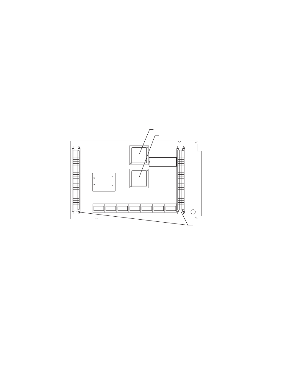
Figure 2-3 shows the Galaxy Vector Controller board. This
board consists of an embedded microcontroller, A/D converters,
timers, memory, and input/output alarm and control circuitry
with connections to the terminal connection boards. There are
two versions of the control board: GCM2 for +24V systems, and
GCM3 for -48V systems. IC27 is the memory IC that contains
the firmware which determines the controller operation, and the
preset voltage and temperature thresholds for plant operation.
Software is updated by replacing IC27. A simpler upgrade
method is to replace the controller board. This avoids directly
handling, and possibly causing damage to the memory IC. There
are no hardware user-configurable items on the GCM boards.
Figure 2-3: Galaxy Vector Controller GCM2 or GCM3
J1 and J3 - Connect to
BLJ3 or BTJ2 Boards
IC27 - Peripheral Support and Memory IC
IC1 - Microcontroller
+
IN
OUT-
OUT+
J1
J3
User Interface
Control Panel
Figure 2-4 shows a view of the 848597563 user interface control
panel. This assembly interfaces with the BLJ3 or BTJ2/BTJ3
connection boards via a 26 pin ribbon attached to P2. The
848597563 provides a comprehensive user interface to the
controller. It is used to view plant voltage and load, configure
thresholds and other system parameters, view active alarms and
to initiate system operations. This interface consists of a 4 line x
20 alphanumeric character LCD, a nine key keypad, and three
status LEDs. A standard DB9 connector is available for local
terminal access, or remote access using an optional BSM3
modem board. The modem board also provides isolation to the
local terminal connection. Note: If the BSM3 is not connected