Table 2-d: blj3 alarm input terminals, Table 2-e: lvd contactor configuration jumpers – GE Industrial Solutions Galaxy Vector Controller GCM3 User Manual
Page 22
Galaxy Vector Controller GCM2, GCM3
2 - 8 Product Description
Issue 4 January 2008
SH3+, SH3-, SH4+, SH4-, V2+, V2-, V3+, V3-, V4+, V4-, B1,
B2, M1, M2: These input terminals are not used by the Vector
controller.
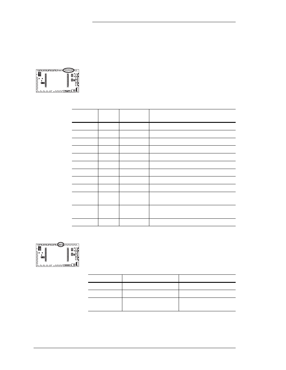
Alarm input (IN1 - IN12): Basic office and contactor state
alarm inputs. Individual pin descriptions are shown in Table
2-D.
Table 2-D: BLJ3 Alarm Input Terminals
Terminal
Name
Alarm
Asserted
Description
IN1
FAJ
Closure to Batt Fuse major alarm input
IN2
FAN
Not used
IN3
OS
Not used
IN4
MAINT
Open to Batt Maintenance (open connector)
IN5
AMJ
Closure to Batt Auxiliary major alarm input
IN6
AMN
Not used
IN7
LVD1C
Not used
IN8
LVD2C
Not used
IN9
LVD3C
Not used
IN10
LVD1O Closure to Batt
Low voltage disconnect contactor 1 open
status input
IN11
LVD2O Closure to Batt
Low voltage disconnect contactor 2 open
status input
IN12
LVD3O
Not used
J1, J2, J3: LVD1, LVD2, and LVD3 contactor configuration
jumpers used to detect the presence of contactors. Table 2-E
shows configuration information.
Table 2-E: LVD Contactor Configuration Jumpers
Jumper
Across Pins 1 and 2
Across Pins 2 and 3
J1
LVD1 present
LVD1 not present
J2
LVD2 present
LVD2 not present
J3
LVD3 present
(not available)
LVD3 not present
(default for GCM)