Rainbow Electronics DS2153Q User Manual
Page 21
DS2153Q
022697 21/48
additional bits from the TLINK pin. If the user wishes to
pass the Sa bits through the DS2153Q without them
being altered, then the device should be set up to source
all five Sa bits via the TLINK pin and the TLINK pin
should be tied to the TSER pin. Please see the timing
diagrams and the transmit data flow diagram in Section
13 for examples.
7.0 SIGNALING OPERATION
The Channel Associated Signaling (CAS) bits
embedded in the E1 stream can be extracted from the
receive stream and inserted into the transmit stream by
the DS2153Q. Each of the 30 channels has four signal-
ing bits (A/B/C/D) associated with it. The numbers in
parenthesis () are the channel associated with a particu-
lar signaling bit. The channel numbers have been
assigned as described in the ITU documents. For
example, channel 1 is associated with timeslot 1 and
channel 30 is associated with timeslot 31. There is a set
of 16 registers for the receive side (RS1 to RS16) and 16
registers on the transmit side (TS1 to TS16). The
signaling registers are detailed below.
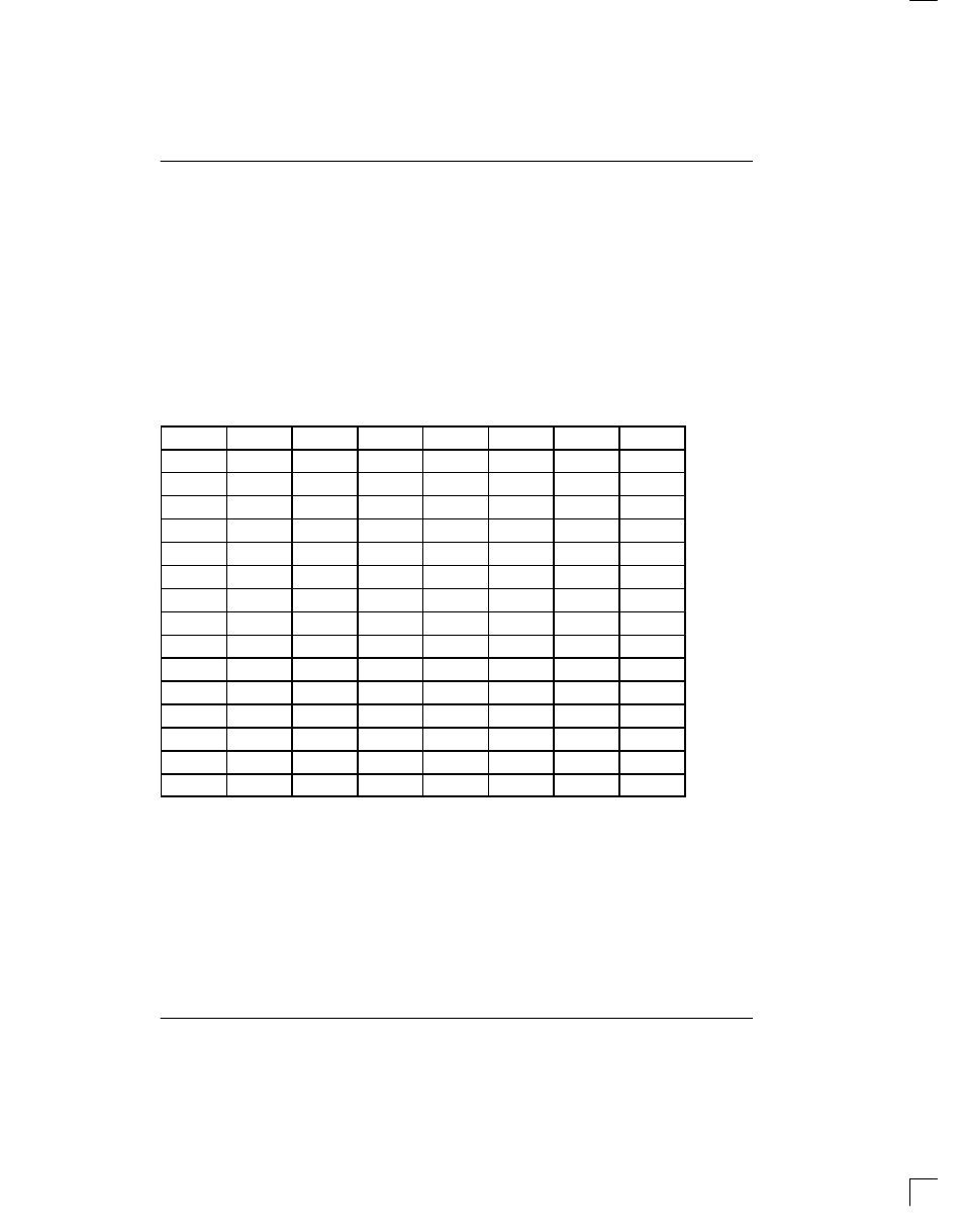
RS1 TO RS16: RECEIVE SIGNALING REGISTERS (Address=30 to 3F Hex)
(MSB)
(LSB)
0
0
0
0
X
Y
X
X
A(1)
B(1)
C(1)
D(1)
A(16)
B(16)
C(16)
D(16)
A(2)
B(2)
C(2)
D(2)
A(17)
B(17)
C(17)
D(17)
A(3)
B(3)
C(3)
D(3)
A(18)
B(18)
C(18)
D(18)
A(4)
B(4)
C(4)
D(4)
A(19)
B(19)
C(19)
D(19)
A(5)
B(5)
C(5)
D(5)
A(20)
B(20)
C(20)
D(20)
A(6)
B(6)
C(6)
D(6)
A(21)
B(21)
C(21)
D(21)
A(7)
B(7)
C(7)
D(7)
A(22)
B(22)
C(22)
D(22)
A(8)
B(8)
C(8)
D(8)
A(23)
B(23)
C(23)
D(23)
A(9)
B(9)
C(9)
D(9)
A(24)
B(24)
C(24)
D(24)
A(10)
B(10)
C(10)
D(10)
A(25)
B(25)
C(25)
D(25)
A(11)
B(11)
C(11)
D(11)
A(26)
B(26)
C(26)
D(26)
A(12)
B(12)
C(12)
D(12)
A(27)
B(27)
C(27)
D(27)
A(13)
B(13)
C(13)
D(13)
A(28)
B(28)
C(28)
D(28)
A(14)
B(14)
C(14)
D(14)
A(29)
B(29)
C(29)
D(29)
A(15)
B(15)
C(15)
D(15)
A(30)
B(30)
C(30)
D(30)
SYMBOL
POSITION
NAME AND DESCRIPTION
X
RS1.0/1/3
Spare Bits
Y
RS1.2
Remote Alarm Bit (integrated and reported in SR1.6)
A(1)
RS2.7
Signaling Bit A for Channel 1
D(30)
RS16.0
Signaling Bit D for Channel 30
Each Receive Signaling Register (RS1 to RS16) reports
the incoming signaling from two timeslots. The bits in
the Receive Signaling Registers are updated on multi-
frame boundaries so the user can utilize the Receive
Multiframe Interrupt in the Receive Status Register 2
(SR2.7) to know when to retrieve the signaling bits. The
user has a full 2 ms to retrieve the signaling bits before
the data is lost. The RS registers are updated under all
RS1 (30)
RS2 (31)
RS3 (32)
RS4 (33)
RS5 (34)
RS6 (35)
RS7 (36)
RS8 (37)
RS9 (38)
RS10 (39)
RS11 (3A)
RS12 (3B)
RS13 (3C)
RS14 (3D)
RS15 (3E)
RS16 (3F)