Rainbow Electronics DS2153Q User Manual
Page 19
DS2153Q
022697 19/48
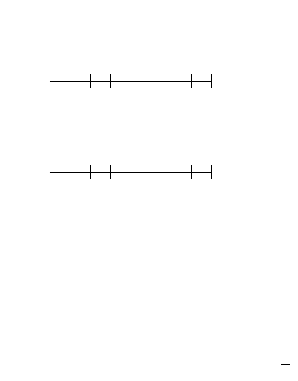
VCR1: UPPER BIPOLAR VIOLATION COUNT REGISTER 1 (Address=00 Hex)
VCR2: LOWER BIPOLAR VIOLATION COUNT REGISTER 2 (Address=01 Hex)
(MSB)
(LSB)
V15
V14
V13
V12
V11
V10
V9
V8
V7
V6
V5
V4
V3
V2
V1
V0
SYMBOL
POSITION
NAME AND DESCRIPTION
V15
VCR1.7
MSB of the 16–bit bipolar or code violation count
V0
VCR2.0
LSB of the 16–bit bipolar or code violation count
5.2 CRC4 Error Counter
CRC4 Count Register 1 (CRCCR1) is the most signifi-
cant word and CRCCR2 is the least significant word of a
10–bit counter that records word errors in the Cyclic
Redundancy Check 4 (CRC4). Since the maximum
CRC4 count in a one second period is 1000, this counter
cannot saturate. The counter is disabled during loss of
sync at either the FAS or CRC4 level; it will continue to
count if loss of multiframe sync occurs at the CAS level.
CRCCR1: CRC4 COUNT REGISTER 1 (Address=02 Hex)
CRCCR2: CRC4 COUNT REGISTER 2 (Address=03 Hex)
(MSB)
(LSB)
(note 1)
(note 1)
(note 1)
(note 1)
(note 1)
(note 1)
CRC9
CRC8
CRC7
CRC6
CRC5
CRC4
CRC3
CRC2
CRC1
CRC0
SYMBOL
POSITION
NAME AND DESCRIPTION
CRC9
CRCCR1.1
MSB of the 10–bit CRC4 error count
CRC0
CRCCR2.0
LSB of the 10–bit CRC4 error count
NOTES:
1. The upper six bits of CRCCR1 at address 02 are the most significant bits of the 12–bit FAS error counter.
5.3 E–Bit Counter
E–bit Count Register 1 (EBCR1) is the most significant
word and EBCR2 is the least significant word of a 10–bit
counter that records Far End Block Errors (FEBE) as
reported in the first bit of frames 13 and 15 on E1 lines
running with CRC4 multiframe. These count registers
will increment once each time the received E–bit is set to
zero. Since the maximum E–bit count in a one second
period is 1000, this counter cannot saturate. The
counter is disabled during loss of sync at either the FAS
or CRC4 level; it will continue to count if loss of multi-
frame sync occurs at the CAS level.
VCR1
VCR2
CRCCR1
CRCCR2