Hardware connections, Safety warnings, Front panel – ZyXEL Communications ZyXEL Dimension GS-3012 User Manual
Page 39: Chapter 3 hardware connections, 1 safety warnings, 2 front panel
GS-3012/GS-3012F User’s Guide
Hardware Connections
3-1
Chapter 3
Hardware Connections
This chapter acquaints you with the front and rear panels, shows you how to make the connections,
install/remove (optional) modules and explains the LEDs.
3.1 Safety Warnings
The length of exposed (bare) power wire should not exceed 7mm.
Do not use this product near water, for example, in a wet basement.
Only a qualified technician should service or disassemble this device.
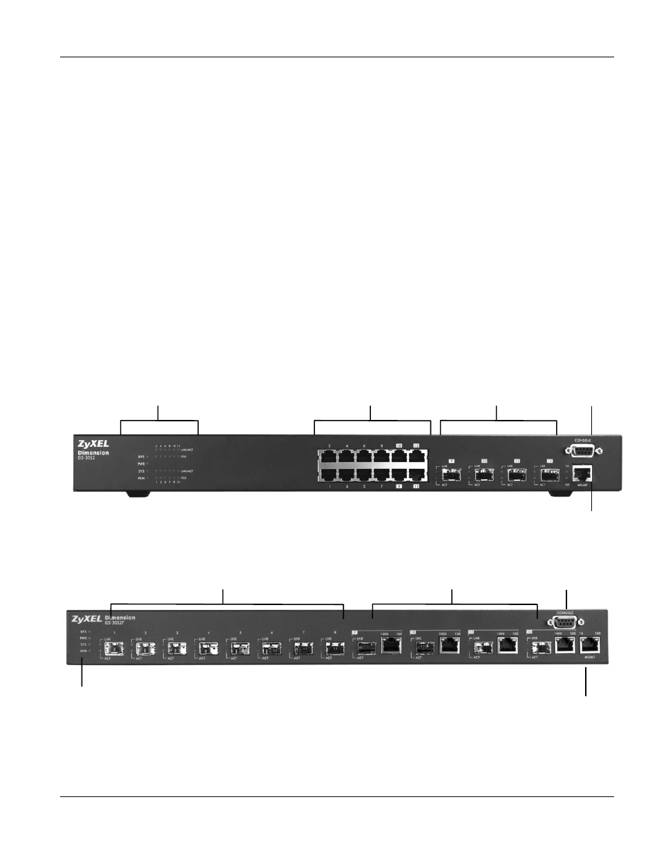
3.2 Front Panel
The following figure shows the front panel of the GS-3012. The front panel contains the switch LEDs, RJ-45
gigabit ports, mini GBIC ports and a console and management port for local management.
Figure 3-1 GS-3012 Front Panel
The following figure shows the front panel of the GS-3012F. The front panel contains the switch LEDs, mini GBIC
ports, RJ-45 Gigabit ports, and a console and management port for local management.
Figure 3-2 GS-3012F Front Panel
LEDs
Mini GBIC/ Ethernet Combo Ports
Mini GBIC Ports
Console Port
Management Port
LEDs
Ethernet Ports
Mini GBIC Ports
Console Port
Management Port