Product preview – Texas Instruments TMS320C6454 User Manual
Page 38
www.ti.com
PRODUCT PREVIEW
TMS320C6454
Fixed-Point Digital Signal Processor
SPRS311A – APRIL 2006 – REVISED DECEMBER 2006
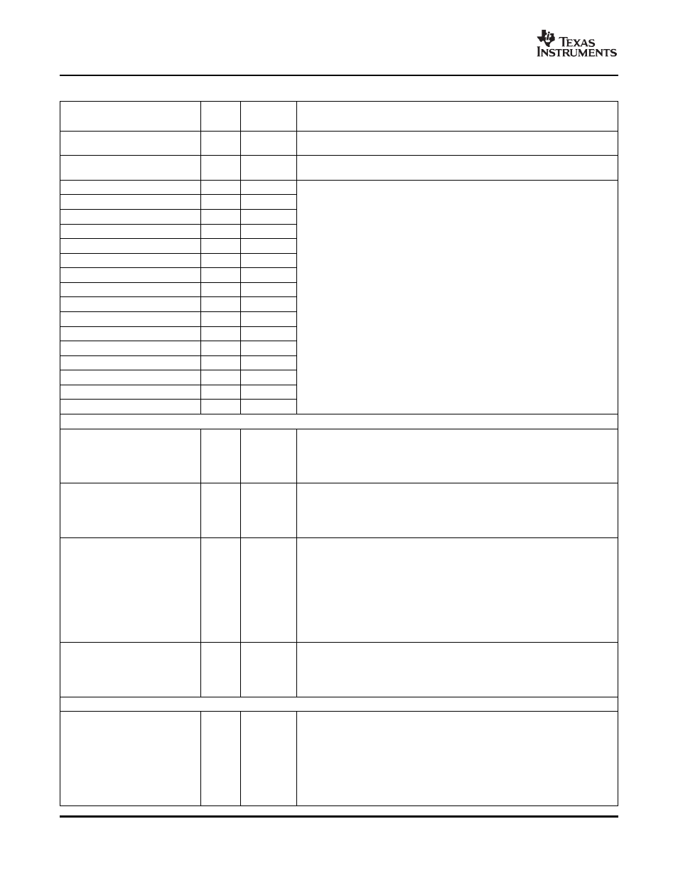
Table 2-3. Terminal Functions (continued)
SIGNAL
TYPE
(1)
IPD/IPU
(2)
DESCRIPTION
NAME
NO.
Reserved. This pin must be connected to the 1.8-V I/O supply (DV
DD18
) via a
RSV34
E6
1-k
Ω
resistor for proper device operation.
Reserved. This pin must be connected directly to ground for proper device
RSV35
D6
operation.
RSV63
AD20
I
RSV64
AC15
I
RSV65
AC17
I
RSV66
AD16
I
RSV67
U16
I
RSV68
V15
I
RSV69
V17
I
RSV70
W16
I
Reserved. These pins must be connected directly to V
SS
for proper device
operation.
RSV71
W18
I
RSV72
AE17
I
RSV73
AE19
I
RSV74
AE23
I
RSV75
AF20
I
RSV76
AH20
I
RSV77
AJ17
I
RSV78
AJ23
I
SUPPLY VOLTAGE MONITOR PINS
Die-side 1.2-V core supply (CV
DD
) voltage monitor pin. The monitor pins
indicate the voltage on the die and, therefore, provide the best probe point for
CV
DDMON
N1
voltage monitoring purposes. For more information regarding the use of this
and other voltage monitoring pins. If the CV
DDMON
pin is not used, it should be
connected directly to the 1.2-V core supply (CV
DD
).
Die-side 3.3-V I/O supply (DV
DD33
) voltage monitor pin. The monitor pins
indicate the voltage on the die and, therefore, provide the best probe point for
DV
DD33MON
L6
voltage monitoring purposes. For more information regarding the use of this
and other voltage monitoring pins. If the DV
DD33MON
pin is not used, it should
be connected directly to the 3.3-V I/O supply (DV
DD33
).
Die-side 1.5-/1.8-V I/O supply (DV
DD15
) voltage monitor pin. The monitor pins
indicate the voltage on the die and, therefore, provide the best probe point for
voltage monitoring purposes. For more information regarding the use of this
and other voltage monitoring pins. If the DV
DD15MON
pin is not used, it should
be connected directly to the 1.5-/1.8-V I/O supply (DV
DD15
).
DV
DD15MON
F3
I
NOTE: If the RGMII mode of the EMAC is not used, the DV
DD15
, DV
DD15MON
,
V
REFHSTL
, RSV13, and RSV14 pins can be connected directly to ground (V
SS
)
to save power. However, connecting these pins directly to ground will prevent
boundary-scan from functioning on the RGMII pins of the EMAC. To preserve
boundary-scan functionality on the RGMII pins, see
.
Die-side 1.8-V I/O supply (DV
DD18
) voltage monitor pin. The monitor pins
indicate the voltage on the die and, therefore, provide the best probe point for
DV
DD18MON
A26
voltage monitoring purposes. For more information regarding the use of this
and other voltage monitoring pins. If the DV
DD18MON
pin is not used, it should
be connected directly to the 1.8-V I/O supply (DV
DD18
).
SUPPLY VOLTAGE PINS
(DV
DD18
/2)-V reference for SSTL buffer (DDR2 Memory Controller). This input
voltage can be generated directly from DV
DD18
using two 1-k
Ω
resistors to form
a resistor divider circuit.
NOTE: The DDR2 Memory Controller is not used, the V
REFSSTL
, RSV11, and
V
REFSSTL
C14
A
RSV12 pins can be connected directly to ground (V
SS
) to save power.
However, connecting these pins directly to ground will prevent boundary-scan
from functioning on the DDR2 Memory Controller pins. To preserve
boundary-scan functionality on the DDR2 Memory Controller pins, see
.
Device Overview
38