Ntak20 clock controller (cc) daughterboard – Nortel Networks Circuit Card User Manual
Page 837
NTRB21 DTI/PRI/DCH TMDI card
Page 837 of 906
Circuit Card
Description and Installation
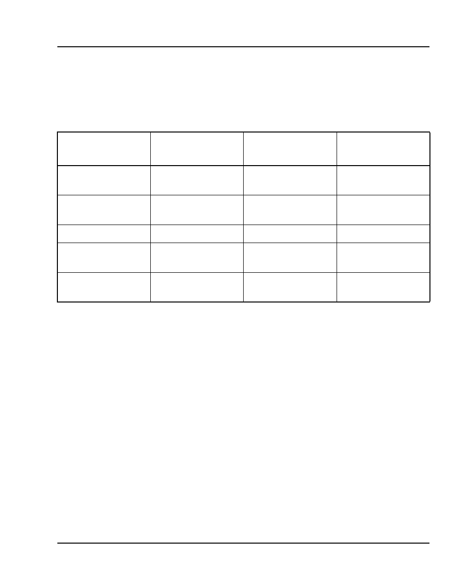
Connector pinout
The connection to the external digital carrier is through a 15 position Male
D-type connector.
NTAK20 Clock Controller (CC) daughterboard
Digital Trunking requires synchronized clocking so that a shift in one clock
source results in an equivalent shift of the same size and direction in all parts
of the network.
The NTAK20 clock controller circuitry synchronizes the CS 1000S,
CS 1000M Cabinet, and Meridian 1 PBX 11C Cabinet to an external
reference clock and generates and distributes the clock to the system. The
CS 1000S, CS 1000M Cabinet, and Meridian 1 PBX 11C Cabinet can
function either as a slave to an external clock or as a clocking master to the
network.
The NTAK20AD and NTAK20AA versions of the clock controller meet
AT&T Stratum 3 and Bell Canada Node Category D specifications. The
NTAK20BD and NTAK20BA versions meet CCITT stratum 4
specifications. See “NTAK20 Clock Controller daughterboard” on
Table 265
DS-1 line interface pinout for NTBK04 cable
From 50-pin
MDF connector
To DB-15
Signal name
Description
pin 48
pin 1
T
transmit tip to
network
pin 23
pin 9
R
transmit ring to
network
pin 25
pin 2
FGND
frame ground
pin 49
pin 3
T1
receive tip from
network
pin 24
pin 11
R1
receive ring from
network