Nortel Networks Circuit Card User Manual
Page 70
Page 70 of 906
Overview
553-3001-211 Standard 3.00 August 2005
trunk line through an impedance matching and balance network. The trunk
interface also includes the logic necessary to place outgoing call signaling
onto the trunk, or the logic to connect to special services such as recorded
announcement and paging equipment.
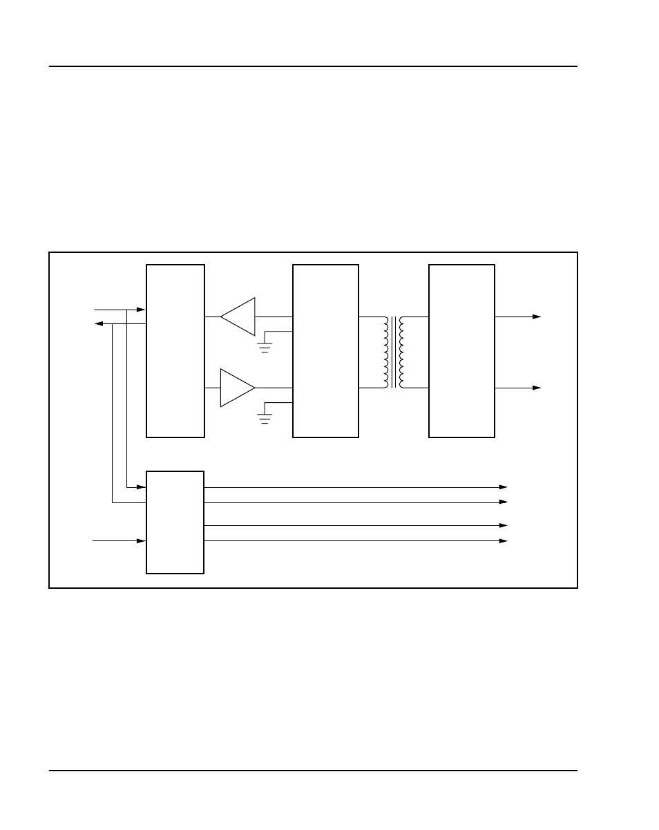
Figure 14 shows a typical example of the logic that performs these functions.
Each part of the trunk interface unit is discussed in the following section.
Coder/Decoder circuit
The coder/decoder (codec) performs Analog to Digital (A/D) and Digital to
Analog (D/A) conversion of the line analog voiceband signal to and from a
digital PCM signal. This signal can be coded and decoded using either the
A-Law or the µ-Law companding algorithm. On some trunk cards the
decoding algorithm depends of the type of codec installed when the board is
built. On others, it is an option selected using a software overlay.
Figure 14
Typical trunk interface unit block diagram
CODEC
2-wire
to
4-wire
conversion
and
balance
network
Interface
(protection)
Variable gain
filters
Isolation
transformer
Ring
TS0
Tip
DS-30X
Network loop
553-6159
Signaling
leads
(E&M,
DX, etc.)
Signaling
logic