Functional description, System considerations – Nortel Networks Circuit Card User Manual
Page 670
Page 670 of 906
NT8D41AA Serial Data Interface Paddle Board
553-3001-211 Standard 3.00 August 2005
Functional description
The NT8D41AA SDI paddle board has two asynchronous serial ports. These
serial ports are connected to the I/O panel in the back of the shelf using special
adapter cables. The serial ports can be used to connect the system to a
terminal, a printer, a modem, or to an other system processor.
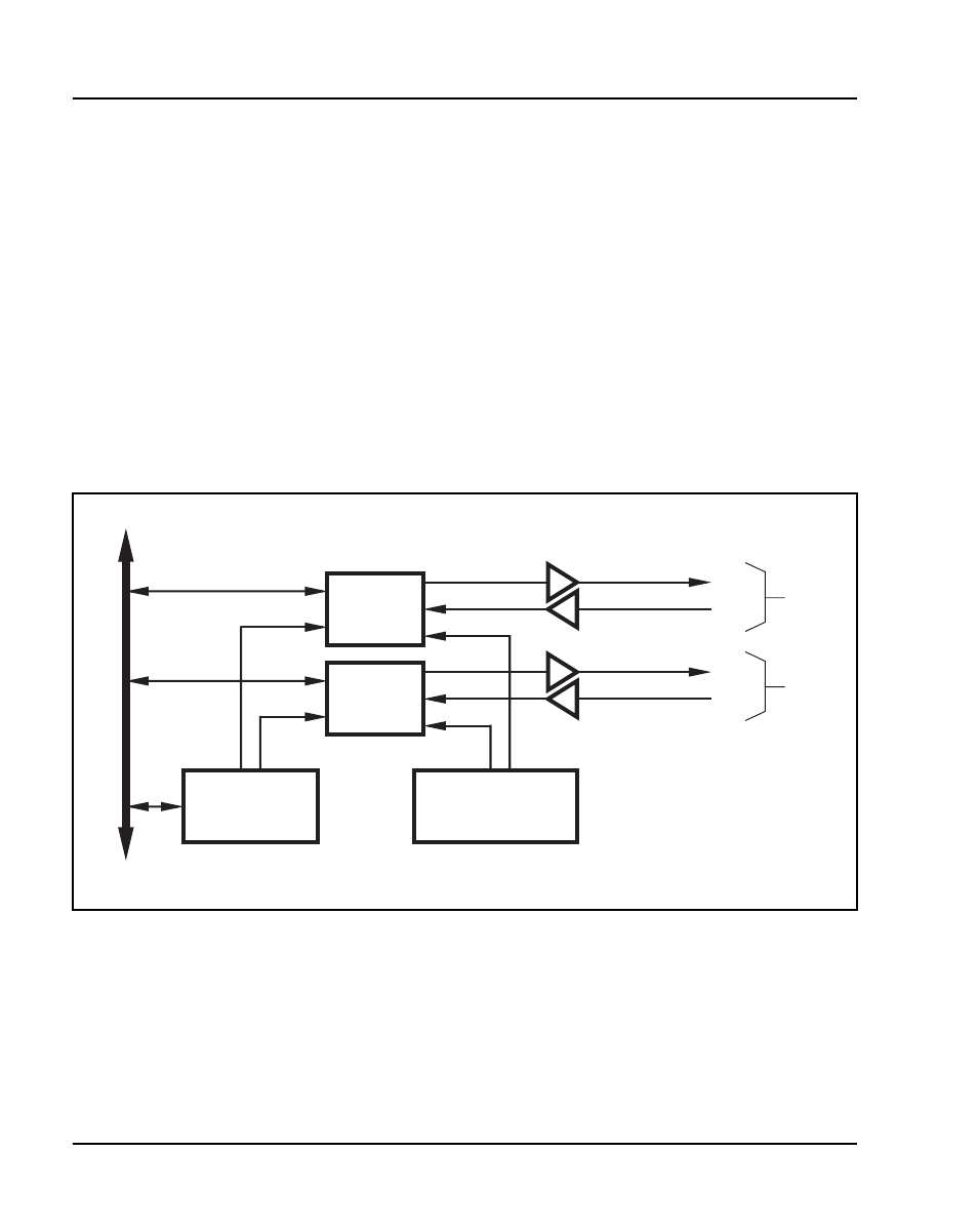
The SDI paddle board contains two Universal Asynchronous Receiver/
Transmitters (UARTs) and the logic necessary to connect the UARTs to the
system processor bus. See Figure 158. Other logic on the card includes two
baud rate generators, two RS-232-C driver/receiver pairs, and the switches
and logic needed to configure the UARTs.
System considerations
In dual-processor systems, the SDI paddle board will behave differently
depending on which backplane socket it is installed in. Installing the paddle
board into a socket in the network area of the backplane allows it to work
when either of the system processors is active. Installing the paddle board into
Figure 158
NT8D41AA SDI paddle board block diagram
UART
no. 2
UARTs
Address
decode logic
TD
RD
TD
RD
RS-232-C
drivers and receivers
Clock and bit
rate select logic
Control
bus
553-5980
Port 1
(J1)
Port 2
(J2)
UART
no. 1