Nortel Networks DCT1900 User Manual
Page 360
Technical Product Manual - DCT1900
Maintenance, Test and Maintenance Software
2-10
Maint-DCT1900/R8/mw
© 2000-2005
PO
: Power–on
all boards
: means all boards, except the CPU +
: counter increments by 1
WD
: Watch–dog
NA
: Not Applicable
0
: counter reset
REL
: Relative
P
: Peripheral
=
: not changed
ABS
: Absolute
BC
: Board Controller
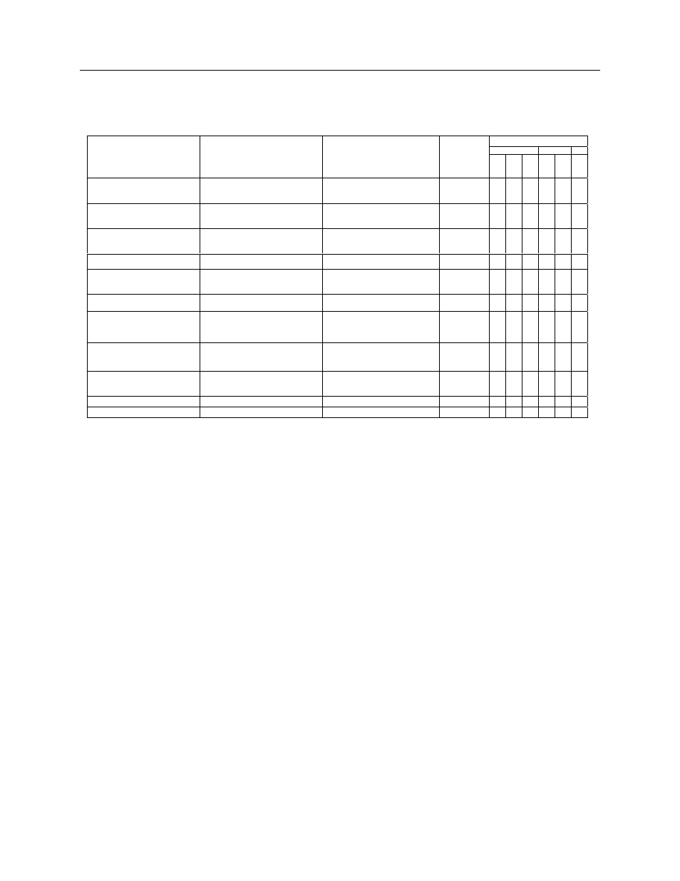
Table 2–1 Reset Counters and Error Tables
Reset Counters
CPU
BC
P
Action
Reset type
Results in
Error
Tables
cleared
P
O
W
D
R
E
L
A
B
S
R
E
L
R
E
L
System switched on
CPU power–on Reset
Board power–on Reset
Power–on test CPU
Power–on test all boards
x
+
0
+
0
0
CPU reset button
pressed
CPU power–on Reset
Board power–on Reset
Power–on test CPU
Power–on test all boards
x
+
0
+
0
0
Minimum configuration
lost
Backplane Reset (SW)
Power–on test all boards
+
+
=
Board inserted in system
Board power–on Reset
Power–on test board
+
0
0
Power–on/System test
Board watch–dog Reset
(expected)
Normal termination of test
Error situations:
T&M receives error
message
T&M reset/BC
T&M reset/P
Power–on test board
+
=
+
=
=
+
CPU in loop
CPU watch–dog Reset
Power–on test CPU
Power–on test all boards
x
+
0
+
0
0
Board Processor in loop
Board watch–dog Reset
(unexpected)
Power–on test board
+
+
=
Initialization
no reset
NA
x
0
0
0
0
0
0
Board removal
NA
NA
NA
0
0
0
0
0
0