2 modular cabinet powering restrictions, Technical product manual - dct1900 – Nortel Networks DCT1900 User Manual
Page 113
Technical Product Manual - DCT1900
Configuration Directions, Limitations of the System
Config-DCT1900/R8/mw
2-3
© 2000-2005
2.2
Modular Cabinet Powering Restrictions
Although the Modular Cabinet has space for 9 boards, not all board combinations are allowed due
to power limitations of the DC/DC converter on the backplane. This converter is specified as
follows:
+5 V
can supply 40 W at maximum
+12 V
can supply 12 W at maximum
-12 V
can supply 12 W at maximum
total
must be
<
40 W
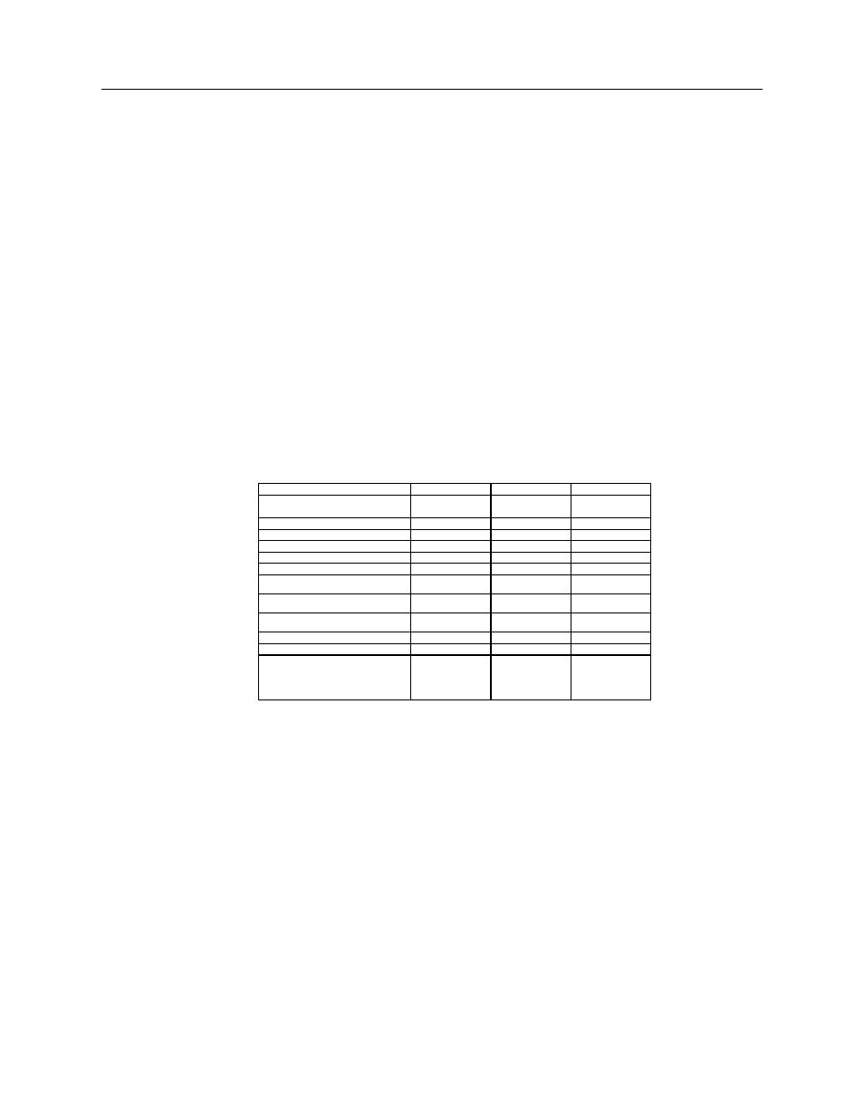
Table 2–1 shows the power consumption per board type. From this table, it can be calculated if a
configuration matches the power requirements. The values given to the
±12V of the LTU indicates
the power consumption in the case where all LTU circuits are off hooks.
Note:
Due to a minimum required power consumption from the DC/DC converter, at least two boards
must be present in each cabinet.
Table 2–1 Power Consumption per Board
B o a r d T y p e
5 V
+ 1 2 V
- 1 2 V
C P U - 2 R E X - B R D 9 0 3 3
R E X - B R D 9 0 3 4
6 W
C P U R E X - B R D 0 0 0 4
9 . 6 W
1 W
1 W
S P U - S R E X - B R D 0 0 1 7
3 . 5 5 W
S L U R E X - B R D 0 0 1 5
6 . 9 W
C L U - S R E X - B R D 0 0 1 6
3 . 4 5 W
C L U R E X - B R D 0 0 1 4
3 . 6 W
D T U - E 1 , C C S / C A S
R E X - B R D 0 0 0 2
4 . 5 W
D T U - T 1 , C A S
R E X - B R D 0 0 2 1
6 W
D T U - T 1 C C S
R E X - B R D 0 0 2 1
6 W
L T U R E X - B R D 0 0 0 7
1 . 5 W
. 7 5 W
. 7 5 W
L T U - 2 R E X - B R D 0 0 1 9
2 . 5 W
D L U R E X - B R D 0 0 2 3
A W S 1 0 2 4
A W S 1 0 2 5
A W S 1 0 2 6
6 . 5 W
1 . 2 W