2 installation - dtu-e1 – Nortel Networks DCT1900 User Manual
Page 290
Technical Product Manual - DCT1900
Installation Instructions, Modular Cabinet – DTU Cabling
22-2
Install-DCT1900/R8/mw
© 2000-2005
22.2
Installation - DTU-E1
Connecting the DTUs to the MS/PBX
1.
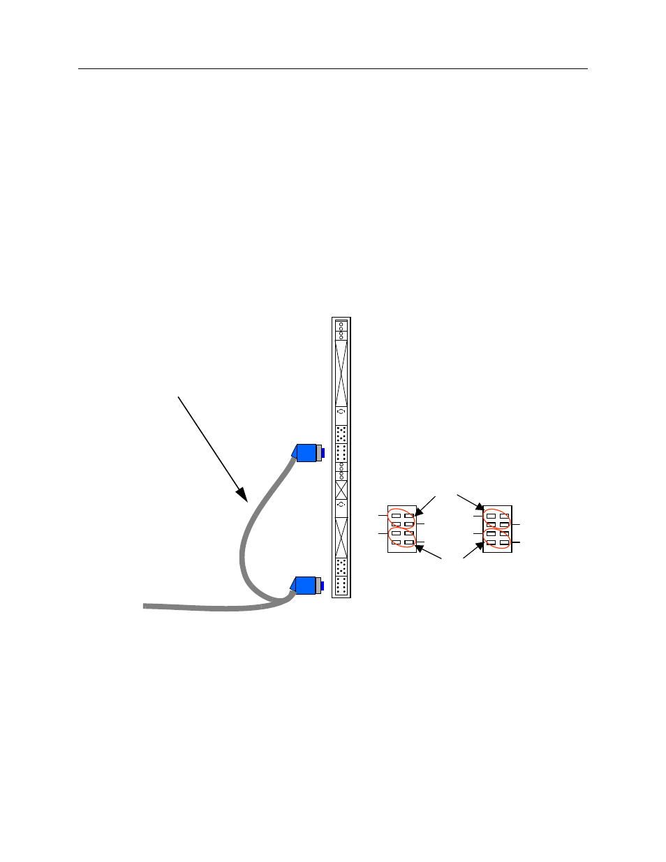
Ensure the DTU strap settings are in the twisted pair position (refer to Chapter 11).
2.
Connect the lower X2 plug of DTU twisted pair cable AWS1034 to the lower connector of the
DTU as shown in Figure 22–2.
3.
Connect the upper X1 plug of DTU twisted pair cable to the upper connector.
4.
Screw the shielding clamp of the cable to the furthest left free position on the ground strip
using two M3 x 10 torx 10 screws delivered with the Modular Cabinet.
5.
Connect the other end of the DTU cable as required - normally punched down on the Main
Distribution Frame (MDF) or “66” block.
Fig. 22–2 DTC Connections on the DTU-E1
Dual DTU E1 cable
AWS1034
X1
WHT
WHT
WHT
BRN
GRN
1 2
7
8
WHT
WHT
ORN
BLU
1 2
7
8
WHT
WHT
WHT
ORN
BLU
1 2
7
8
X2
X1
RCV
pairs
XMIT
pairs
View looking into DTU board edge
X2
- T7316 (188 pages)
- T7316E (2 pages)
- T7316 (2 pages)
- i2050 (56 pages)
- NN10300-009 (80 pages)
- NN43112-107 (46 pages)
- NN40050-109 (20 pages)
- 1120E (25 pages)
- 4065R (92 pages)
- Enterprise Edge M7324N (6 pages)
- 2007 (54 pages)
- NN42030-102 (78 pages)
- LDP7004 (1 page)
- MCC 3100 (78 pages)
- LIP-6812 (21 pages)
- 1120 (160 pages)
- CallPilot Desktop Messaging (72 pages)
- Companion MICS-XC (138 pages)
- jAZZ X-6000 (28 pages)
- Meridian M3901 (2 pages)
- Meridian M3902 (146 pages)
- NN42030-101 (108 pages)
- P0609347 02 (8 pages)
- BCM50 (280 pages)
- i2021 Series (77 pages)
- 3100 (72 pages)
- BCM1000 (347 pages)
- C3050 REV2 (42 pages)
- N0035509 (90 pages)
- Enterprise Edge Feature Programming Telephone (170 pages)
- Meridian M3904 (2 pages)
- 6300 (138 pages)
- NN42030-107 (112 pages)
- ATA 2 (16 pages)
- IP Phone 2002 (2 pages)
- 414X (52 pages)
- BST Doorphone (18 pages)
- Regular Telephone (27 pages)
- M2008HF (74 pages)
- Business Communications Manager (BCM) & Norstar Installation (81 pages)
- 1000E (468 pages)
- M2016S (24 pages)
- 2050 (46 pages)
- CallPilot 150 (68 pages)
- BSG12 (2 pages)