Nortel Networks DCT1900 User Manual
Page 125
Technical Product Manual - DCT1900
Configuration Directions, Base Station Powering
Config-DCT1900/R8/mw
4-5
© 2000-2005
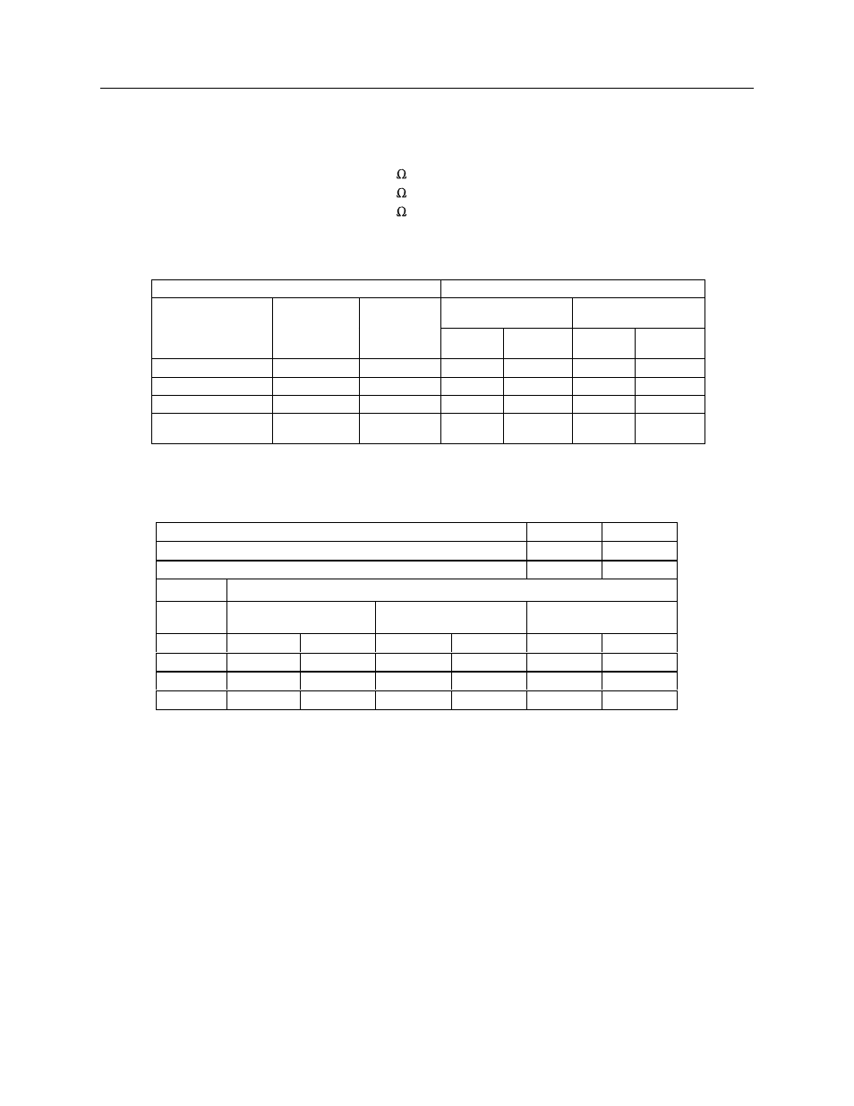
The following resistance values for the twisted pairs are used:
z
26 AWG wire cable
: .082 /ft.
z
24 AWG wire cable
: .055 /ft.
z
22 AWG wire cable
: .034 /ft.
Tables
Table 4–1 "Data Limited" Cable Length
* Cable lengths should never exceed the values given in Table 4–1, because of data limitations
Table 4–2 Maximum Cable Length when Powering via Data Pairs and Express Powering Pairs
Cable
Maximum cable length
Superimposed noise
8 mV/pHz
Superimposed noise
10 mV/pHz
Type
Wire size (
∅)
AWG
Capacitance
CLU
11/2
SLU
CLU-s
CLU
11/2
SLU
CLU-s
Twisted pair
26ga
15 pF/ft.
7540 ft.
4920 ft.
6560 ft.
4260 ft.
Twisted pair
24ga
15 pF/ft.
11480 ft.
6880 ft.
9840 ft.
6230 ft.
Twisted pair
22ga
40 pF/ft.
6880 ft.
4260 ft.
5900 ft.
3930 ft.
Double twisted pair
(J–Y (St)Y 2 2 0.6)
22ga
40 pF/ft.
6160 ft.
3930 ft.
4920 ft.
3280 ft.
Worst Case Power Consumption of Base Station =
7.5
W
Based pm Class 3 =
23
dbm
Minimum Input Voltage of Base Station =
21
V
Maximum Cable Length (feet)
Wire size
(
∅)
Power Supply Voltage
27.5 V
Power Supply Voltage
42 V
Power Supply Voltage
48 V
0 EPP
1 EPP
0 EPP
1 EPP
0 EPP
1 EPP
26 awg
418
627
1405
2107
1842
2763
24 awg
627
941
2107
3161
2763
4145*
22 awg
1026
1539
3448*
5172*
4522*
6782*