Front panel display – Powerware 9170+ User Manual
Page 66
Operation
62
Powerware
®
9170 User's Guide
S
LTM-1344 B Uncontrolled Copy
Front Panel Display
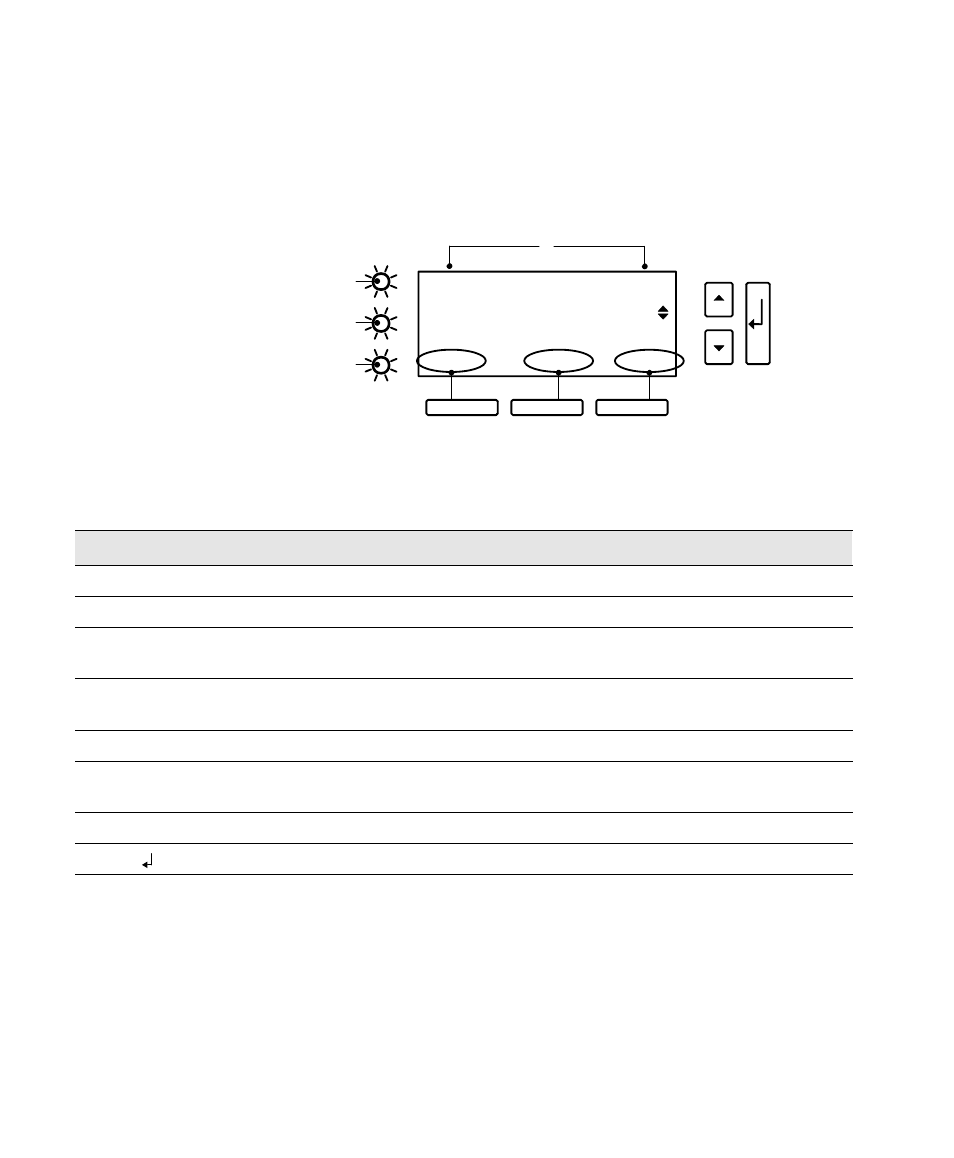
The front panel has an alphanumeric display, three LED indicators, and
six pushbuttons as described in Figure 47 and in Table 7.
3 19 USER #3
Wout
watts 2.07 KW
Slot Top ESC
2
3
4
A
B
C
1
Figure 47. UPS Front Panel
Table 7. Front Panel Details
Item
Description
1
Alphanumeric display of unit function and operating parameters. Also displays alarm/data logs.
2
Alarm LED (red). Illuminates to signal that the unit has detected an alarm condition.
3
Battery LED (yellow). Illuminates to signal that the unit is operating on battery power and producing
output voltage.
4
Line LED (green). Illuminates to signal that the unit is operating on AC utility power and producing
output voltage.
A and B
Multi-function buttons, as labeled by the bottom line of the alphanumeric display.
C
Menu/Escape button, for moving into and out of display menus. Also, for avoiding a change to a
parameter value.
and
Y
B
Menu scroll up and down buttons. Also, for increasing/decreasing parameter value digits.
Enter button, to activate/accept displayed parameter or operating mode.