Powerware 9170+ User Manual
Page 61
UPS Startup
57
Powerware
®
9170 User's Guide
S
LTM-1344 B Uncontrolled Copy
4. The output voltage is the most important operating parameter
you must set as part of the initial configuration screens. Select
the desired UPS output voltage using the
Y
and
B
buttons.
Possible selections are 200, 208, 220, 230, and 240 Vac. (Low
voltages are derived from these voltages, as listed in Table 5 on
page 35 and Table 6 on page 43.) Press the button when the
desired output value is displayed.
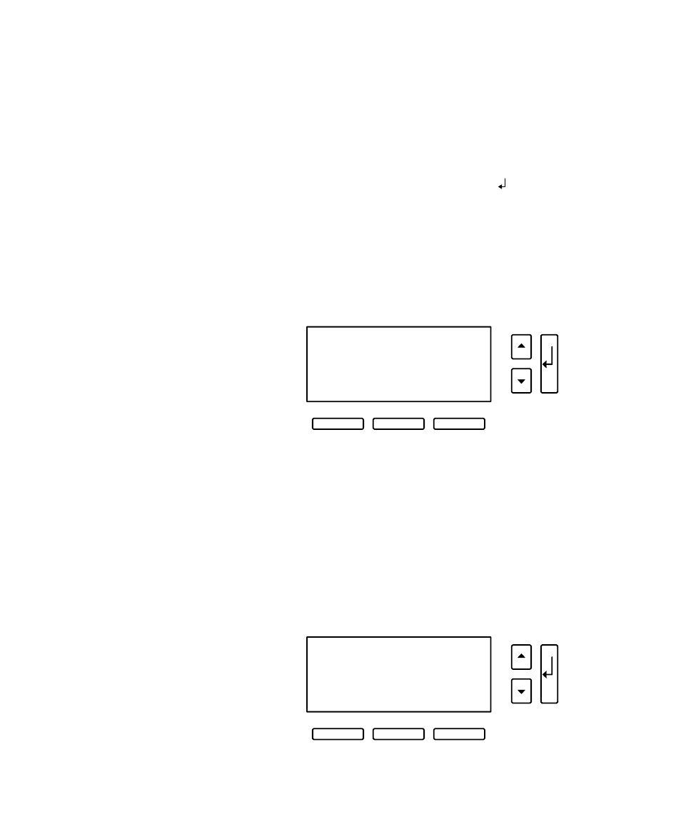
5. If the system includes any external battery cabinets, record the
ampere-hour capacity of batteries installed in these cabinets.
Count the number of battery strings (two battery modules,
side-by-side equals one string). Each battery string contains
7.2 ampere-hours. Enter the total value in the next startup
screen.
External Capacity
extamphr 0028.8
<– –> ESC
6. The system signals an alarm when required output cannot be
maintained with the loss of redundant power modules. The
alarm is essentially disabled with a redundancy level set at 0.
If you want the system to notify you when the number of
redundant power modules is less than a specified level, enter a
redundancy level. Each increment above 0 indicates the
number of modules that can be removed from operation before
the alarm occurs. This setting only affects the alarm; the system
continues to operate as an N+X system even if this parameter is
left at the default value of 0.
Set Redundancy
RSetting 0
<– –> ESC