Rack-mount installation – Powerware 9170+ User Manual
Page 16
Installation Setup
12
Powerware
®
9170 User's Guide
S
LTM-1344 B Uncontrolled Copy
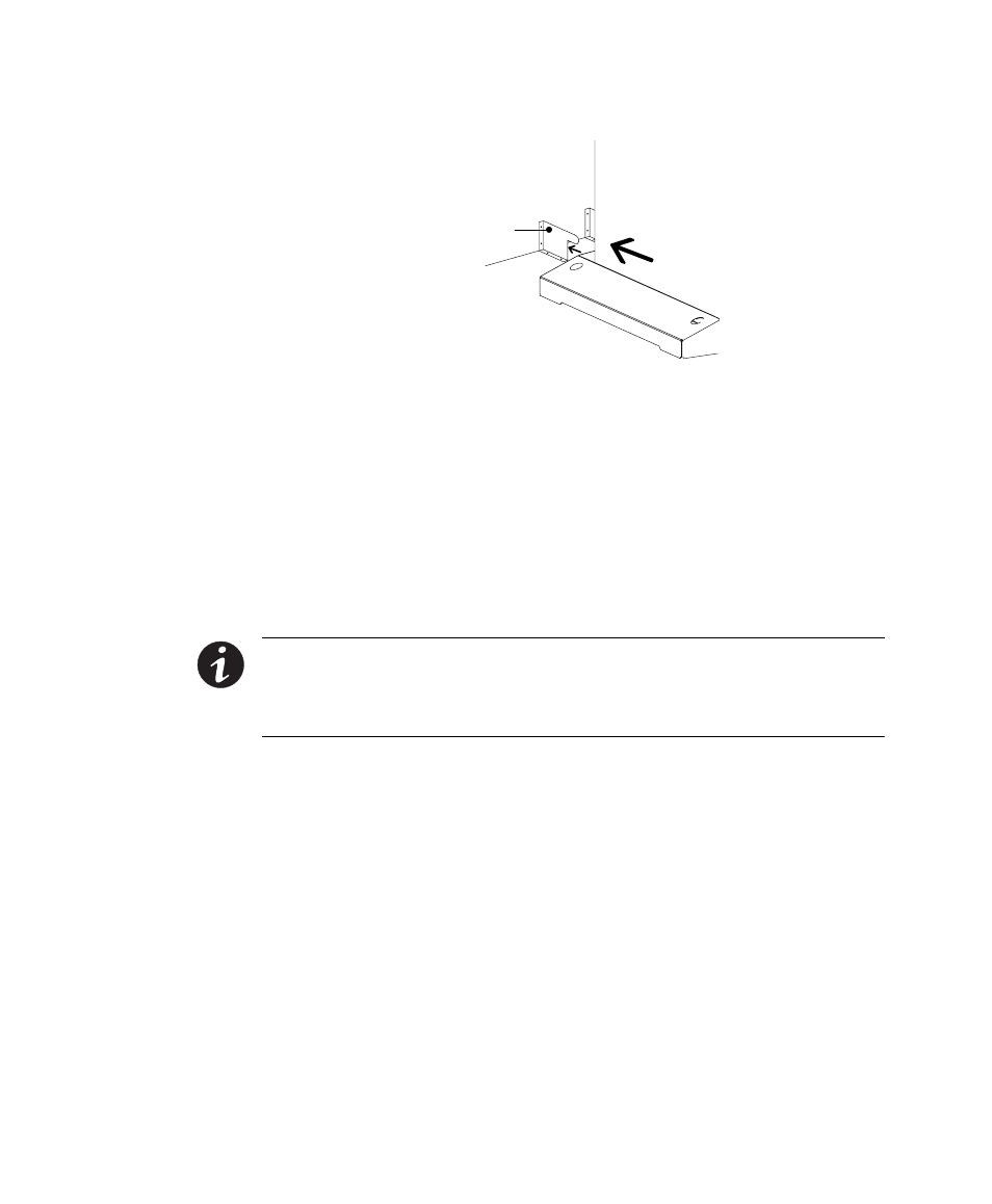
Stabilizer Bracket
Figure 8. Stabilizer Bracket Installation
Rack-Mount Installation
The 3- and 6-slot UPS cabinets may be installed in an EIA-standard 19I
(48.3-cm) equipment rack. An optional rack-mounting kit (ASY-0547),
containing brackets and required hardware, is available for such an
installation. For each 3-slot section, use the following mounting
procedure to convert the UPS cabinet and install it in the equipment
rack:
NOTE The UPS cabinet is heavy. This procedure requires two people to lift and
position the cabinet into the equipment rack. Install the cabinet in the rack before
installing power and battery modules, and before plugging the UPS into the intended
power outlet.
1. Remove the four screws (two on either side) securing the top
cover of the UPS cabinet. Carefully lift the cover straight up and
off, to avoid stressing the front panel display. Set the cover
aside.
2. Remove the two cabinet side panels (4 panels in 6-slot cabinets)
by lifting the top edge. No other hardware must be detached.
Store or discard the side panels.
3. Carefully replace the UPS cabinet top cover and secure with the
four screws removed in Step 1. Position the cover lip to fit
behind the front display panel.
4. Install three metal clip-nuts onto each side flange (6 clip-nuts
on 6-slot cabinets) along the front of the UPS cabinet (see
Figure 9).