Powerware 9170+ User Manual
Page 37
Electrical Installation
33
Powerware
®
9170 User's Guide
S
LTM-1344 B Uncontrolled Copy
3
2
1
+DC
X1
X2
N
-DC
N
-DC
X2
+DC
X1
Backplane Board
Terminating
Studs
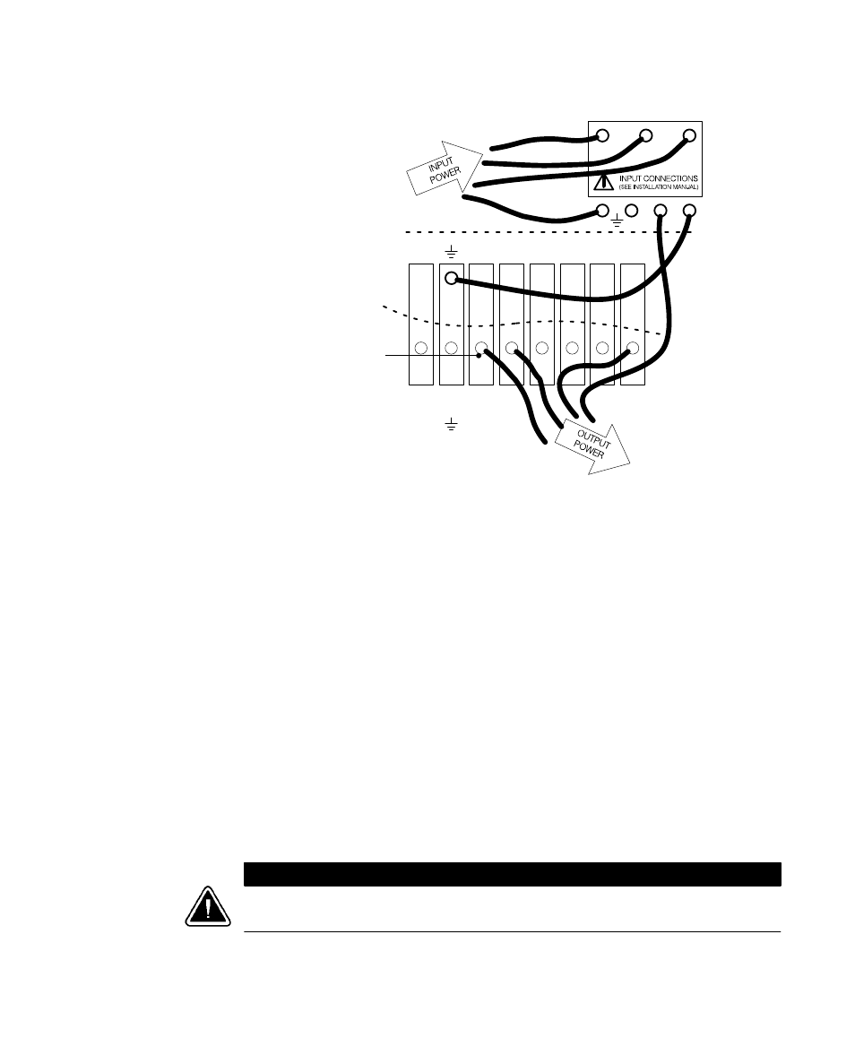
Figure 23. UPS Input and Output Terminals
9. Refer to the wiring diagrams beginning on page 38 which show
output configurations for various voltages and isolation
options. Make UPS output connections on the backplane board
terminating studs. Compression lugs (supplied in the accessory
kit) may be installed on the proper terminating studs. Wires
may also be terminated with ring terminals, which are attached
to the output terminating studs.
10. If the bypass switch is an MBB style, notice the cable routed out
of the left side of the bypass switch cabinet. The red and black
pair of wires (normally open) in this cable must be connected
to terminals 3 and 4 in Steps 11 and 12. (Do not connect the
white and black pair of wires in this cable.)
11. If any external, hardwired control signals are required, remove
the rear panel on the upper section of the cabinet and locate the
terminal block, as shown in Figure 24.
C
A
U
T
I
O
N
EPO and external bypass circuits are not isolated from line voltage, and wiring must be
installed according to local codes using conduit or suitable primary supply cables.