Powerware 9170+ User Manual
Page 17
Installation Setup
13
Powerware
®
9170 User's Guide
S
LTM-1344 B Uncontrolled Copy
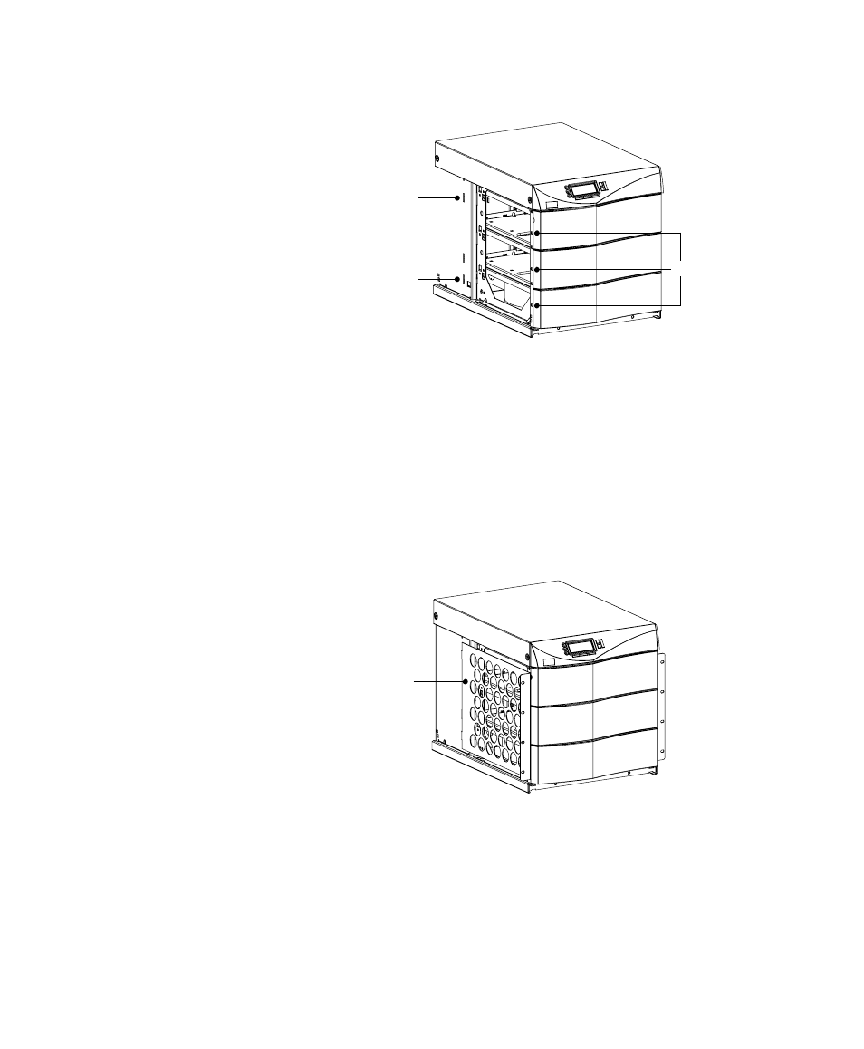
Tab Slots
Metal Clip-Nuts
Figure 9. Metal Clip-Nut and Tab Slot Locations
5. Install a rack-mount ear (2 for 6-slot cabinets) on each side of
the UPS cabinet (see Figure 10).
Insert the two offset tabs on the rear edge of the ear into the
matching tab slots on the cabinet side frame (see Figure 9).
Pivot the ear forward, until it is flush against the UPS cabinet
side frame. Secure each ear with three 1/4-20 1/2I
Phillips-head bolts, screwed into the metal clip-nuts installed in
Step 4.
Rack-Mount Ear
Figure 10. Rack-Mount Ear Installed
6. Select the position for the UPS in the equipment rack.
7. Install one equipment rail on each side of the rack using four
10-32 1/2I flat-head screws per rail. Select the proper holes in
the rail that position the UPS at the desired location in the rack
(see Figure 11).