Powerware 9170+ User Manual
Page 36
Electrical Installation
32
Powerware
®
9170 User's Guide
S
LTM-1344 B Uncontrolled Copy
5. Install the conduit adapters. AC input and AC output
conductors must be run through separate conduits. UPS output
circuits must be installed in dedicated conduit systems and not
shared with other electrical circuits.
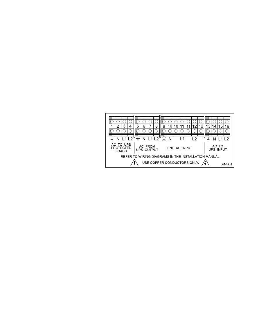
6. Find the terminal strip inside the bypass switch cabinet. Using
the label on the back of the bypass switch access panel and the
proper installation wiring diagram, make the terminal strip
connections and tighten all connections as specified in Table 2
on page 27. Use copper wire that is the appropriate size for the
current draw. Figure 22 shows a sample label.
Figure 22. Bypass Switch Wiring Label
7. After installing bypass switch wiring, torque the screws holding
all input and output power conductors to the values specified
in Table 2 on page 27.
8. If your UPS has an isolated output, find the proper output
neutral-to-ground connection in the output wiring diagrams
beginning on page 44.
At the UPS terminals,
connect the neutral-to-ground
(neutral-to-earth) wire to the proper terminal before making any
other connections to the UPS
. The neutral-to-ground wire is a
green and yellow wire. One end of this wire is already
connected to the ground (earth) UPS terminal. Ground
terminations, inside the UPS rear panel, are located directly
below the line input terminals. Figure 23 shows input and
output wiring terminals inside the Powerware 9170 UPS
cabinet. Figure 36 on page 45 shows the N-G bond wire
connections.