Powerware 9170+ User Manual
Page 40
Electrical Installation
36
Powerware
®
9170 User's Guide
S
LTM-1344 B Uncontrolled Copy
C
A
U
T
I
O
N
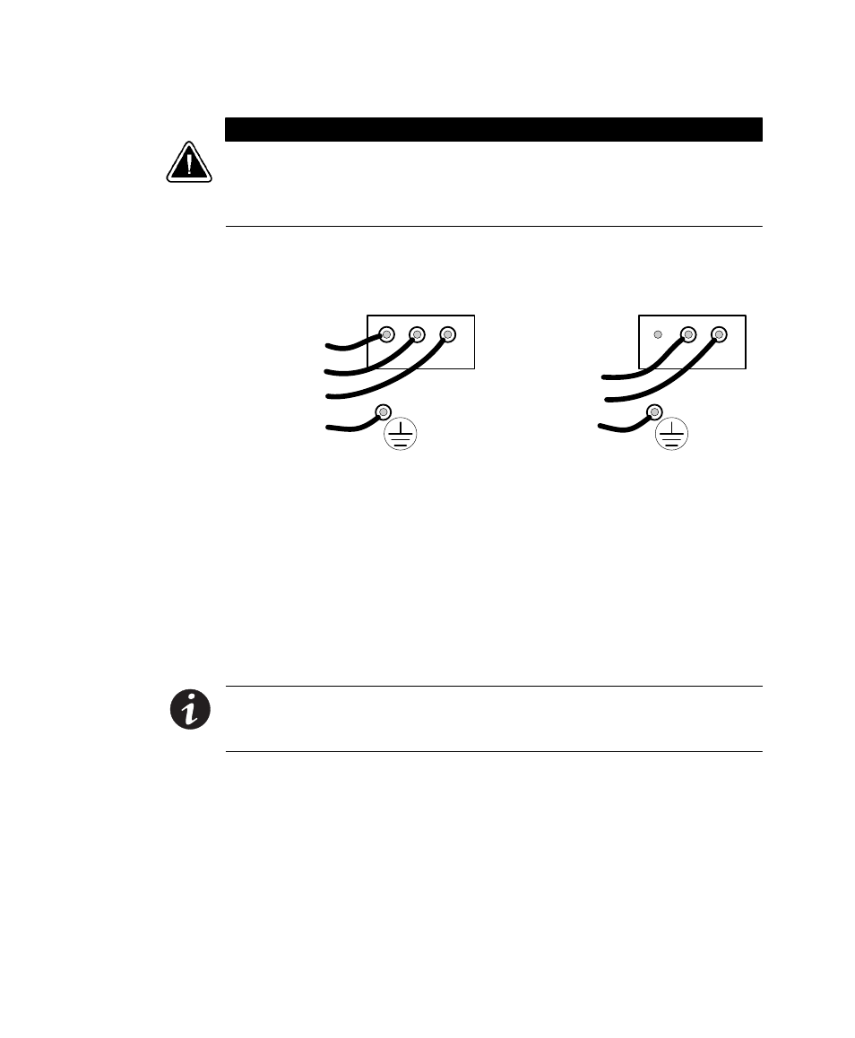
Confirm that the UPS is wired for the proper input voltage as shown in Figure 25, and
that the proper power modules (either universal or split-phase) are installed to produce
the desired output voltage. Do not mix the two types of power modules in the same
UPS cabinet.
(b) Universal Power Modules
(2-Wire Plus Ground Input)
208, 220, 230, and 240 Vac
(a) Split-Phase Power Modules
(3-Wire Plus Ground Input) (2 PEN)
100/200, 110/220, 120/208, 120/240, 127/220 Vac
3
2
1
3
2
1
L2
L1
N
GND
L1
L2/N
GND
Figure 25. UPS Input Wiring
UPS Output Wiring Connections (Non-Isolated Installations)
Figure 26 and Figure 27 describe output wiring configurations for
various output voltages. Use Table 5 to find the desired wiring diagrams
and connect the output AC wiring to the proper Powerware 9170 system
power terminals. You must also set the operating menu parameter 7-3-4
for the required output voltage as shown in the wiring configuration
drawings.
NOTE All power modules in the Powerware 9170 UPS cabinet must be of the same
type: Universal (single-phase) modules have white labels; split-phase modules have
blue labels. Output for each type of module must be wired differently.