Powerware 9170+ User Manual
Page 22
Battery Cabinet Installation
18
Powerware
®
9170 User's Guide
S
LTM-1344 B Uncontrolled Copy
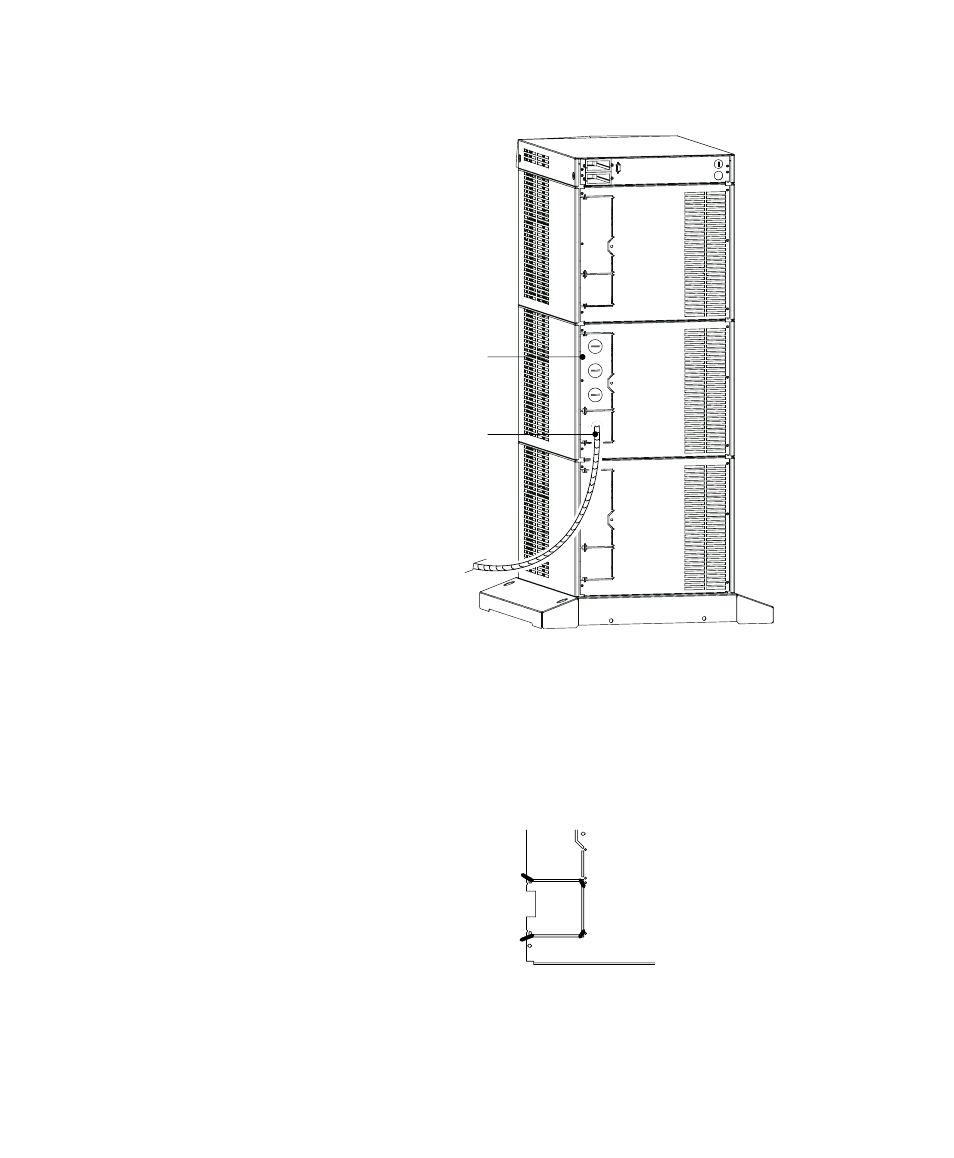
Entrance Panel
Battery Cable
Figure 13. UPS Power Entrance Panel
3. Use a pair of pliers to bend the narrow links (1 and 2 in
Figure 14) between the outer edge of the lower breakaway
panel and the rear panel.
4. Use the pliers to bend the entire breakaway panel (at 3 and 4 in
Figure 14) until it breaks away.
1
2
3
4
Figure 14. Breakaway Panel Links
5. Verify all hazardous voltages have been removed from the
backplane by testing with a voltmeter or other test device.
See also other documents in the category Powerware Tools:
- 5110 (14 pages)
- UPS 1000 - 2200 (24 pages)
- 9 (70 pages)
- 9155 UPS20-30kVA (52 pages)
- 8 - 15 kVA (46 pages)
- 9125 Two-in-One UPS 5000 (66 pages)
- Model V-2000B (137 pages)
- 9335 (100 pages)
- 9120 (5 pages)
- 5115RM (24 pages)
- P93 (6 pages)
- 9390 UPS 100160 kVA (216 pages)
- Horsepower Computer System ST-2400S (17 pages)
- 9155 (10 pages)
- 9125 Two-in-One UPS 2500 (78 pages)
- 5075 kVA (162 pages)
- 380/220V (72 pages)
- 30-160kVA (48 pages)
- Ferrups FE/QFE 500VA (76 pages)
- FSS-0342J (44 pages)
- 9395 UPS and Plus 1 UPS 650825 kVA (192 pages)
- 9315s (205 pages)
- Ferrups FE/QFE UPS (72 pages)
- 9315 UPS (84 pages)
- 5140 (68 pages)
- 9330 (246 pages)
- 9355 (62 pages)
- BladeUPS none (32 pages)
- 5115A USB (44 pages)
- 9170+ (12 pages)
- 9910 p Series (6 pages)
- 9125 (30 pages)
- 4500 (92 pages)
- 9395 (4 pages)
- X-Slot USB Module (10 pages)
- 9150 (64 pages)
- 5105 (4 pages)