Powerware 9170+ User Manual
Page 38
Electrical Installation
34
Powerware
®
9170 User's Guide
S
LTM-1344 B Uncontrolled Copy
The Generator On signal is isolated from line voltage and can
be treated as NEC Class 2 wiring.
Use 14ć20 AWG, 600V wire (UL) or 14ć26 AWG, 300V wire
(CSA) for all input control signals.
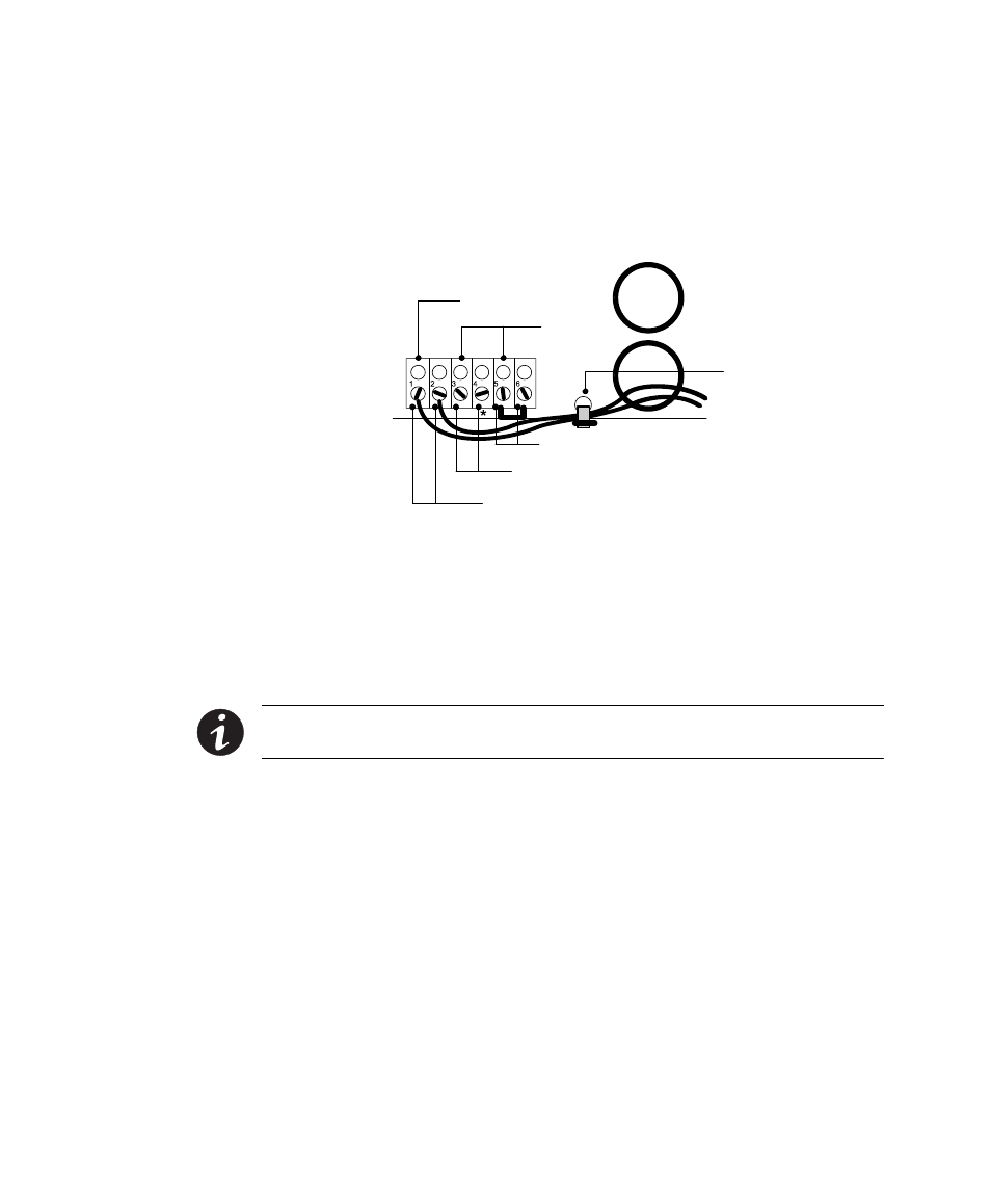
Generator On
(Normally Open)
Signal
Common
Emergency Power-Off (Normally Closed)
External Bypass *(Short to Common When Active)
Generator Set
Plastic Cable Tie
Figure 24. Input Control Signal Wiring
12. Place the signal wires through the proper conduit or grommet
above the terminal block and attach to appropriate terminals.
Secure each connection by torquing terminal screws to a
maximum 3.5 in lb (0.4 Nm). Provide strain relief for cables by
installing plastic cable ties.
NOTE Do not strain relieve EPO or external bypass wiring with the same cable tie
used for Generator On wires.
13. Remove the jumper between terminals 5 and 6 only if you are
wiring from an emergency power-off (EPO) switch. (See
Changing Parameter Settings" on page 65 for information
about accessing menu 7, submenu 1, item 9 to view or change
the EPO switch type.)
14. When all connections have been made and checked, replace the
bypass switch front panel and UPS cabinet rear panels.