Powerware 9170+ User Manual
Page 24
Battery Cabinet Installation
20
Powerware
®
9170 User's Guide
S
LTM-1344 B Uncontrolled Copy
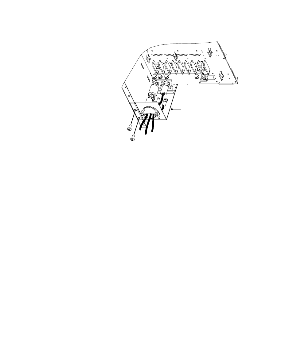
Cable Assembly
Figure 16. Battery Cable Assembly Installation
12. Align the screw holes of the cable assembly's entry plate with
holes on the cabinet side panel as shown in Figure 16. Secure
the entry plate with screws supplied with the cable assembly.
13. If the battery cable will be installed in customer-supplied
flexible or other conduit (as required by local wiring codes),
loosen the two screws holding the strain-relief clamp shown in
Figure 16. Remove the clamp by loosening the star nut on the
inside of the entry plate, leaving the nut in place. Replace the
clamp with a panel-to-conduit feedthrough and secure it with
the star nut.
14. Secure the cable assembly terminals by tightening the nuts onto
the backplane bus bars. Also tighten the third nut, holding the
other fuse end. Torque all three nuts to 75ć85 in lb
(8.5ć9.6 Nm).
15. Replace the UPS cabinet rear panel with the screws removed in
Step 2 on page 17.
16. If the battery cable will be installed in flexible or other conduit,
pull the conductors through the conduit. Attach the conduit to
both the UPS power entrance panel and the battery cabinet
entrance panel as shown in Figure 17.