Centronics interface – Printronix MVP Series User Manual
Page 171
Interfaces
8–3
Centronics Interface
The Centronics (standard) interface transfers parallel data bytes at a rate of
up to 200,000 characters per second. The interface requires an I/O cable
assembly with an Amphenol compatible connector (Printronix P/N
110376–001) as shown in Figure 8–1, connected to the properly terminated
Parallel Controller PCBA at P4. Configuration Option 66 must be set to 66.0
Figure 8–1. Centronics Connector
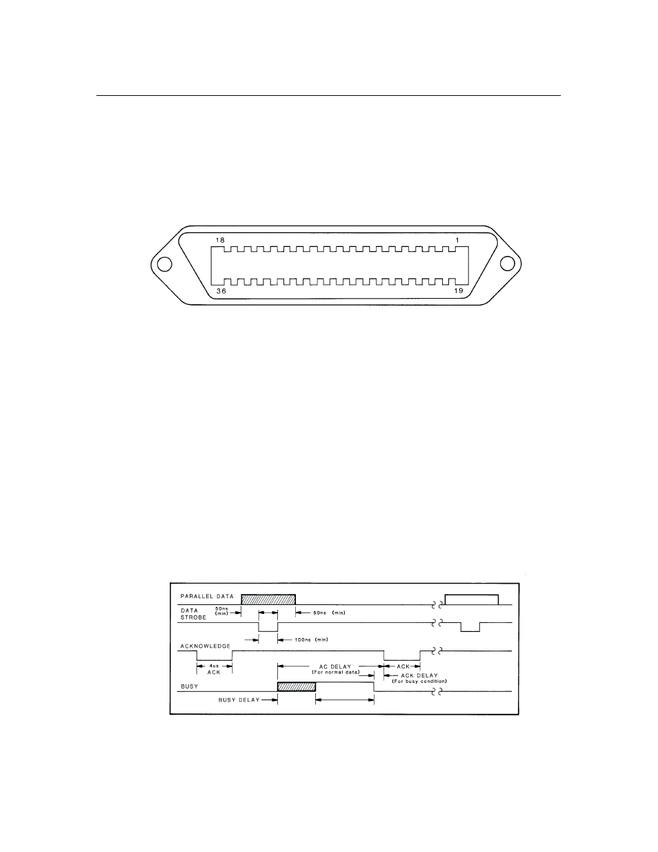
Figure 8–2 illustrates the Centronics interface timing sequence. Data transfer
is initiated when the host computer places a data byte on the data lines. After
a delay of at least 50 ns, the host computer issues DATA STROBE to latch
the data byte into the receiver latches. DATA STROBE must be at least 100
ns in duration. Normally, the printer responds with a 4
µ
s ACKNOWLEDGE
pulse and BUSY. If Configuration Option 65.1 is selected, BUSY will be
suppressed until the host computer sends a line terminator control code byte
(FF, LF, or EVFU). Table 8–1 describes the Centronics interface signals and
pin assignments and Table 8–2 describes the Dataproducts interface signals
and pin assignments.
Figure 8–2. Centronics Interface Timing Sequence