Schneider Electric 890USE17700 User Manual
Page 147
Connection Example
890USE17700 April 2004
147
Request and
Response
Example
The following example uses the data from channel 1 and channel 2 in the
STB AVO 1250 module (node 8 in the sample Advantys STB island bus) (See
Example, p. 142). In the example, Modbus register 40004 corresponds to channel 1
and Modbus register 40005 corresponds to channel 2.
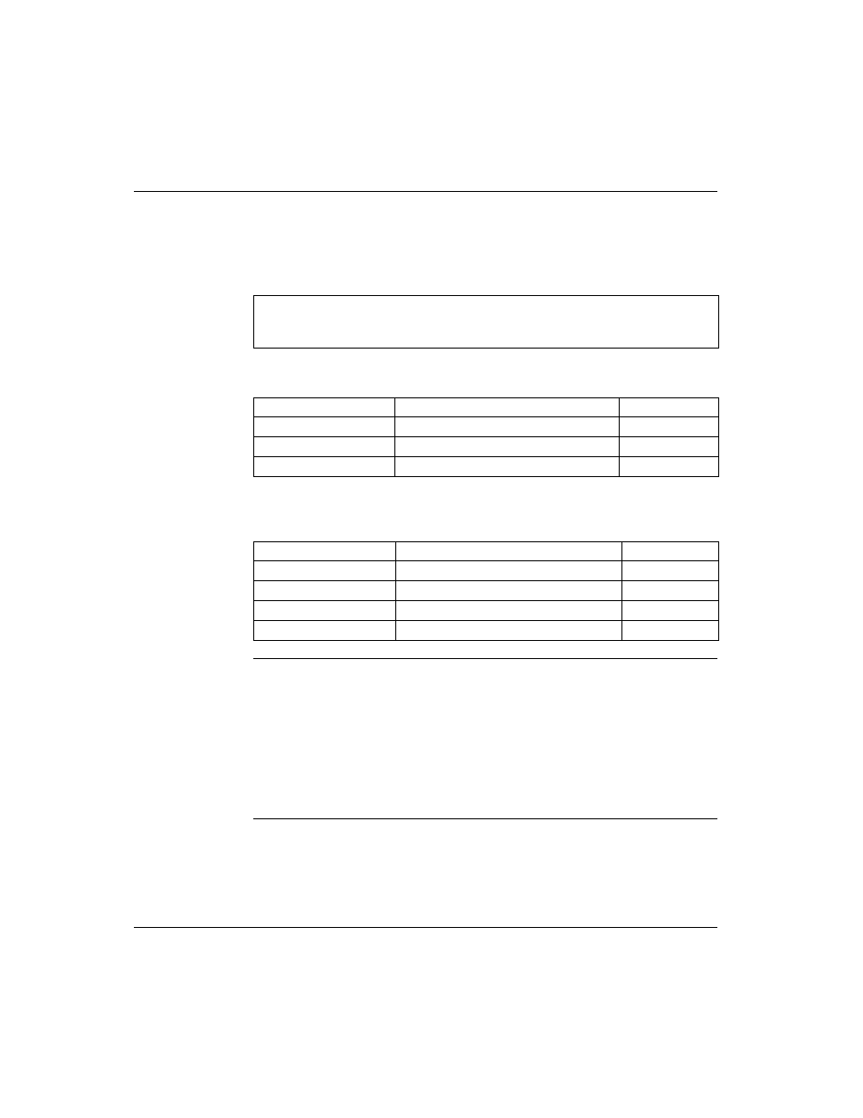
Request: The request determines the starting address and the number of registers
to be read. In this case, two registers—40004 and 40005—should be read:
Response: The response is the reply from the device. It contains the contents of the
registers in which the requested data is located. In this case, register 40004 contains
data 1234, and register 40005 contains data 6789:
Reference
Descriptions
The x’s following the leading character (3/4) represent a four-digit Modbus register
address:
z
3xxxx
Read input registers. A 3x reference register contains a 16-bit number received
from an external source, e.g., an analog signal.
z
4xxxx
Read/write output or holding registers. A 4x reference register is used to store 16-
bits of numerical data (binary or decimal), or to send the data from the CPU to an
output channel.
Note: The examples use hexadecimal notation (0x000) for their numerical format.
Addressing begins in the output process image at register 40001. The format and
addressing may vary according to your particular software and controls.
Description
Field
Example
command
Modbus function code
0x003
register count
word count
0x002
starting point
starting register
0x40004
Description
Field
Example
command
Modbus function code
0x003
register count
word count
0x002
returned value
value of register 40004
0x1234
returned value
value of register 40005
0x6789