Schneider Electric 890USE17700 User Manual
Page 129
Data Exchange
890USE17700 April 2004
129
Node
Configuration
The next eight contiguous registers (registers 45359 through 45366) display
locations where modules have been configured on the island bus. This information
is stored in Flash memory. At start up, the actual locations of the modules on the
island are validated by comparing them to the configured locations stored in
memory. Each bit represents one configured location:
z
A value of 1 in a bit indicates that a module has been configured for the
associated location.
z
A value of 0 in a bit indicates that a module has not been configured for the
associated location.
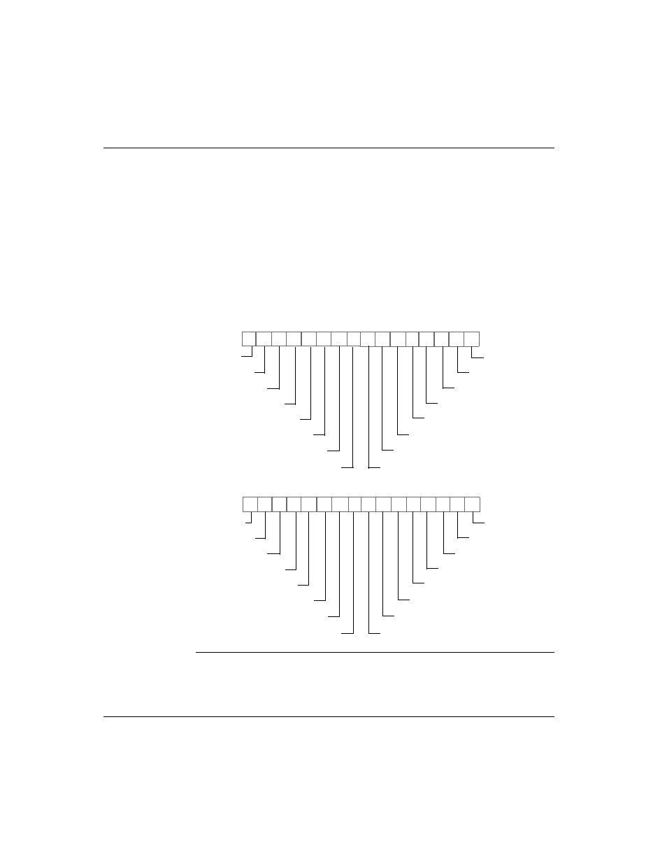
The first two registers, shown below, provide the 32 bits that represent the module
locations available in a typical island configuration. The remaining six registers
(45361 through 45366), are available to support the island’s expansion capabilities:
15 14 13 12 11 10 9 8
7 6 5 4 3 2 1 0
Register 45359
location 1
location 2
location 3
location 4
location 5
location 6
location 7
location 16
location 8
location 9
location 10
location 11
location 12
location 13
location 14
location 15
15 14 13 12 11 10 9 8
7 6 5 4 3 2 1 0
Register 45360
location 17
location 18
location 19
location 20
location 21
location 22
location 23
location 32
location 24
location 25
location 26
location 27
location 28
location 29
location 30
location 31