1 dip-switch setting – IBM RS/6000 User Manual
Page 145
Note
Refer to the
X.25 Interface Co-Processor ISA Adapter Installation Guide
shipped with the adapter for detailed information on this adapter.
6.7.1 DIP-Switch Setting
The X.25 Interface Co-Processor ISA Adapter has a 10-position DIP switch which is
used to set the following parameters:
You do not need to set every DIP switch on the adapter to configure it. The only
DIP switches you have to change are those referring to
Interrupt Level and Bus I/O
Address.
The DIP switches indicating the
Memory Size, Edge Connector and Bus-Width can
be left in the default position set by the factory.
The following table shows the parameter values you may want to select in order to
define the
Interrupt Level and the Bus I/O Address for a conflict-free configuration
of your first, second and third X.25 Co-Processor Adapters.
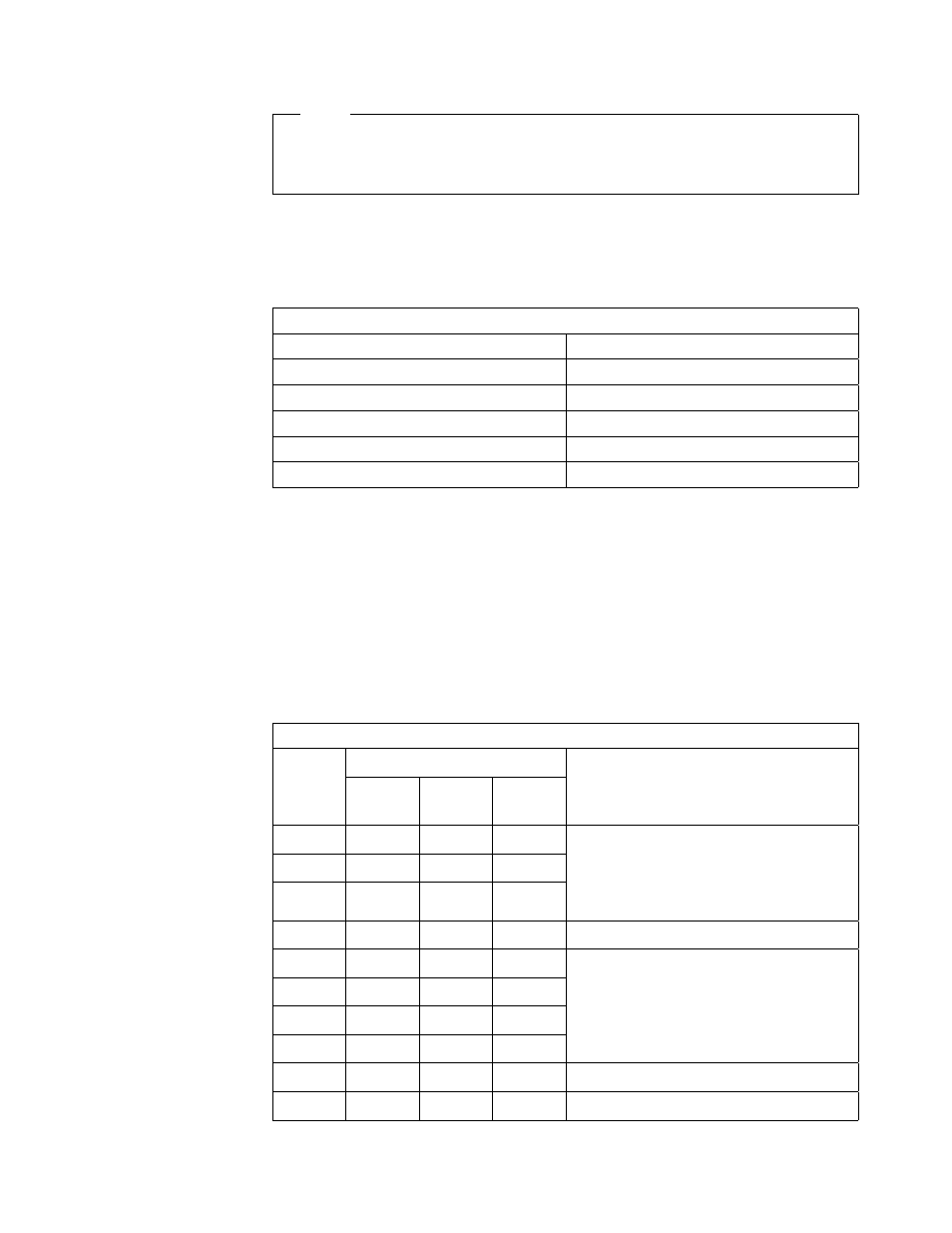
Table 23. DIP Switches on the X.25 Interface Co-Processor ISA Adapter
Parameter
Switch Number(s)
Interrupt Level
1-2-3
Memory Size
4
Bus I/O Address
5-6-7-8
Edge Connector
9
Bus Width
10
Table 24. X.25 Adapter: DIP-Switch Suggested Settings
Dip
Switch
#
Position
Comment
First
Adapter
Second
Adapter
Third
Adapter
1
off
off
on
IRQ Level
First Card: 11
Second Card: 9
Third Card: 7
2
on
off
off
3
off
on
on
4
on
on
on
Memory Size
a
5
on
off
on
I/O Port Address
First Card: 02A0
Second Card: 06A0
Third Card: 0AA0
6
on
on
off
7
on
on
on
8
on
on
on
9
on
on
on
Edge Connector
b
10
on
on
on
Bus-Width
c
Chapter 6. Adapter and Device Configuration on PCI-Based RS/6000 Servers
121