2 dip-switch setting – IBM RS/6000 User Manual
Page 140
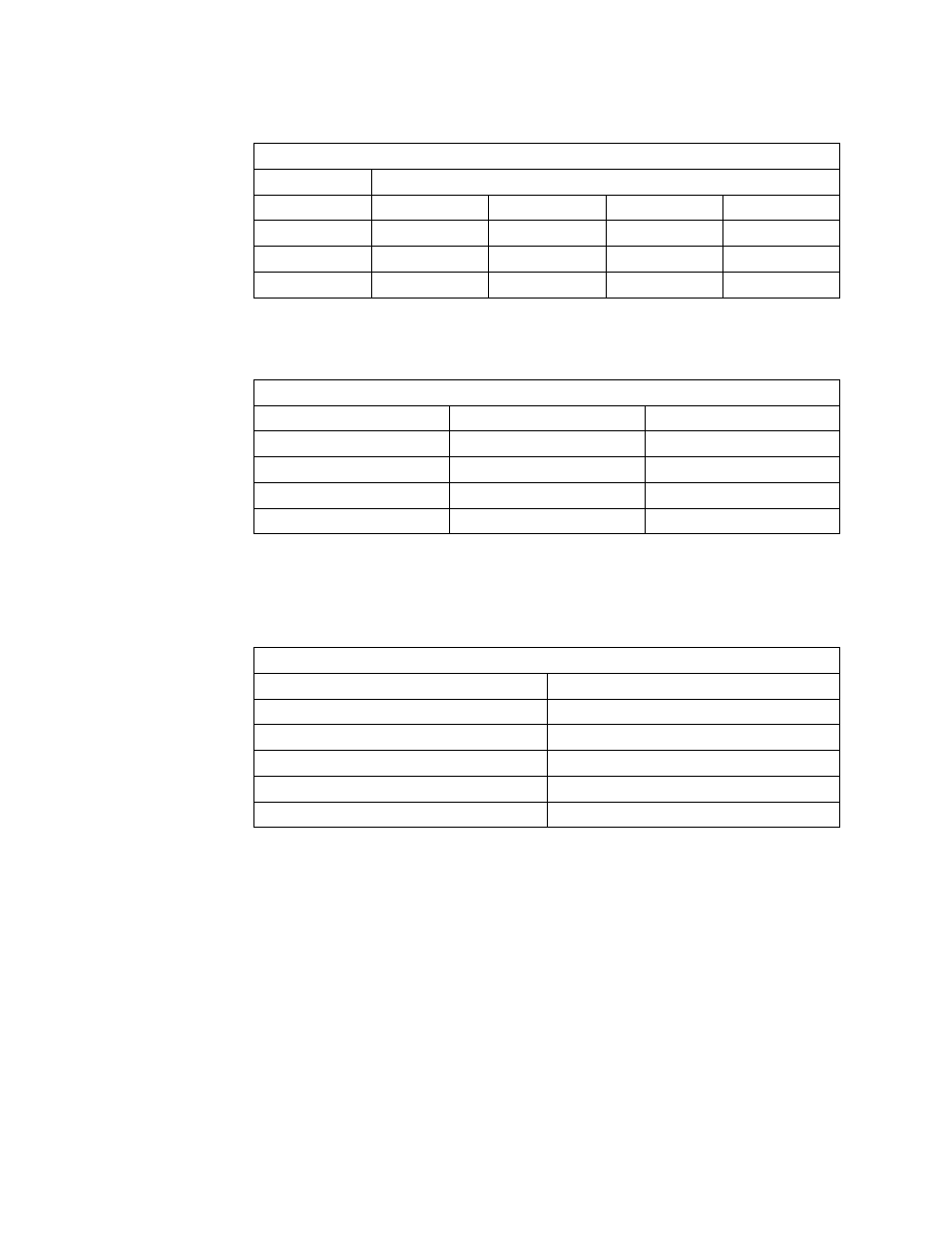
The following table shows the supported interfaces for each port.
The maximum cable lengths that are supported for the various communications
protocols are described in the following table.
Table 19. Physical Interfaces on 4-Port Multiprotocol Interface Cable
Port Number
Supported Interfaces
# 0
EIA-232
EIA-422
V.35
X.21
# 1
EIA-232
-
V.35
-
# 2
EIA-232
EIA-422
-
-
# 3
EIA-232
-
-
-
Table 20. Maximum Cable Length
Protocol
Length (meters)
Length (feet)
RS-232
15.2
50
V.35
15.2
50
RS-422
122
400
X.21
122
400
6.6.2 DIP-Switch Setting
The 4-Port Multi-Protocol ISA Adapter has a 10-position DIP switch which is used
to set the following parameters:
You do not need to set every DIP switch on the adapter to configure it. The only
DIP switches you have to change are those referring to
Interrupt Level and Bus I/O
Address.
The DIP switches indicating the
Memory Size, the Edge Connector and the
Bus-Width can be left in the default position set by the factory.
The following table shows the parameters values you may want to select in order to
define the Interrupt Level and the Bus I/O Address for a conflict-free configuration
of your first, second and third 4-Port Multiprotocol adapters.
Table 21. DIP-Switches on 4-Port Multi-Protocol ISA Adapter
Parameter
Switch Number(s)
Interrupt Level
1-2-3
Memory Size
4
Bus I/O Address
5-6-7-8
Edge Connector
9
Bus Width
10
116
Introduction to PCI-Based RS/6000 Servers