MITSUBISHI ELECTRIC P500YMF-C User Manual
Page 92
–90–
(4)
Troubleshooting the major components of the BC controller
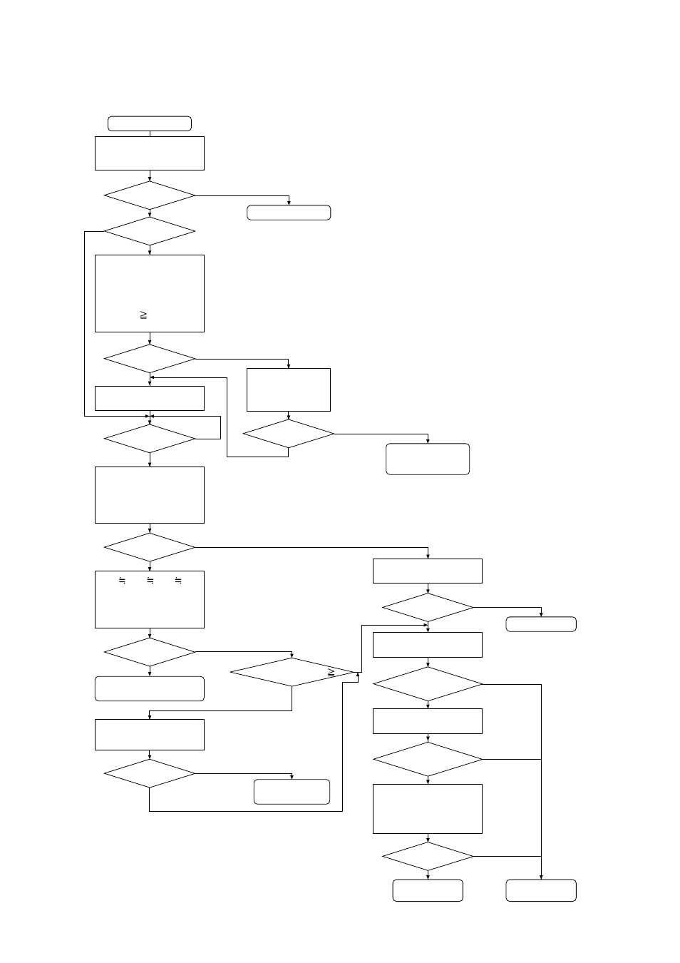
1) Pressure sensor
Pressure sensor troubleshooting flow
Check on the LED monitor dis-
play.
• TH2 or LPS of outdoor unit.
• HPS of outdoor unit
• PS1, PS3 of BC controller and
confirm the following relationship
HPS > PS1
PS3 > TH2 or LPS
(puressure calculated value)
Check that refrigerant pip-
ing and transmission line
connections are in agree-
ment between outdoor
unit and BC controller.
START
Check pressure sensor, PS1,
PS3, connectors for discon-
nection, looseness, or incor-
rect attachment.
OK?
Stop the unit (compres-
sor OFF).
At least
10 minutes passed since
stopping?
Check PS1, PS3 on LED
monitor display and confirm
that none of the detected
pressure values is below
1kg/cm
2
G (0.098MPa).
OK?
OK?
OK?
OK?
Change board.
Repair faulty connection.
Change pres-
sure sensor.
OK?
Replace the wrong
puressure sensor with the
correct pressure sensor, and
confirm It’s detected pres-
sure is indicated correctly.
Short connectors 2 and 3 on the
board and check the pressure.
Pressure
range within 0 to 1kg/cm
2
G
(0.098MPa)
Pressure
of at least 32kg/cm
2
G
(3.14MPa) indicated?
Remove the pressure sensor
connector from the board, and
check the pressure.
Check for faulty connector on
applicable pressure sensor.
Correct refrigerant
piping and trans-
mission line.
OK?
OK?
Note 3
Take corrective action.
HPS PS1 PS3 TH2
or LPS (pressure calcu-
lated value) (The differ-
ence is less than 1kg/
cm
2
G (0.098MPa)
No board or pressure
sensor abnormality.
Check that refrigerant piping and
transmission line connections are
in agreement between outdoor
unit and BC controller.
Confirm the
following relationship PS1
PS3?
Correct refrigerant
piping and the trans-
mission line.
Unit running?
Note 1
No
Note 2
No
No
Note 2
No
No
No
Yes
No
Yes
Yes
Yes
Yes
Yes
Yes
Yes
No
Note 4
No
No
No
Yes
Yes
Yes
No
No
Yes