MITSUBISHI ELECTRIC P500YMF-C User Manual
Page 77
–75–
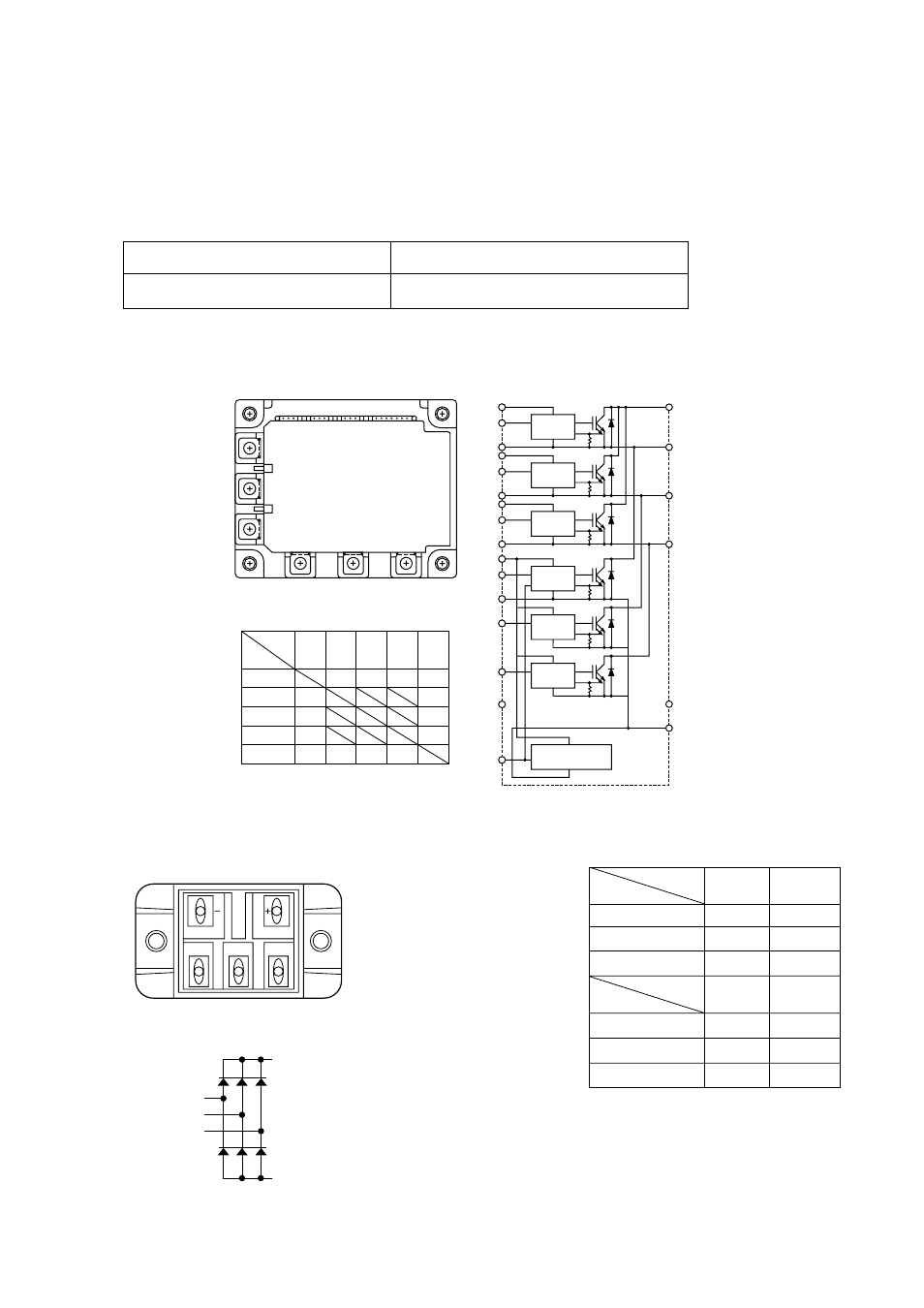
Intelligent Power Module (IPM)
Measure resistances between each terminal of IPM with tester, and use the results for troubleshooting. Specified
resistance value is dependent on tester type to be used for resistance measurement, because diode inside IPM has
non-linearity, thus difference of impedance and voltage in tester being influential. As the internal impedance of
resistance range of analog tester equals to the center value of meter indication, the affect of internal impedance can
be minimized if the tester having close center value of resistance range. Because internal voltage is normally 1.5V,
the tester to be used for troubleshooting of IPM should satisfy the following conditions.
Internal voltage
1.5V (Power source : one dry cell battery)
Central value of resistance range
10 ~ 40
Ω
The measured values for troubleshooting are shown in the table below.
(Use the minimum range for tester resistance range.)
Diode stack
Perform continuity check with tester. Judged as normal if the following characteristics are observed.
(Use the minimum range for tester resistance range.)
1
10~50
Ω
∞
2
10~50
Ω
∞
3
10~50
Ω
∞
1
∞
10~50
Ω
2
∞
10~50
Ω
3
∞
10~50
Ω
1
2
3
1
2
3
+
–
Tester
⊕
Tester
-
+
–
Tester
-
Tester
⊕
+
–
W
P
• External view
• Internal circuit diagram
• Judged value
P
Tester –
Tester
+
U
2~
100
Ω
2~
100
Ω
2~
100
Ω
2~
100
Ω
2~
100
Ω
2~
100
Ω
2~
100
Ω
V
W
∞
∞
∞
N
U
V
W
N
∞
∞
∞
∞
N
P
B
1
4
7
10
16
V
V
U
P
W
N
B
U
3
2
1
6
5
4
9
8
7
11
13
10
14
15
12
16
Pre-Driver
Pre-Driver
Pre-Driver
Pre-Driver
Pre-Driver
Pre-Driver
Over heating
protection circuit