MITSUBISHI ELECTRIC P500YMF-C User Manual
Page 129
–127–
[4] LED Monitor Display
(1)
How to read LED for service monitor
By setting of DIP SW1-1 ~ 1-8, the unit operating condition can be observed with the service LED on the control circuit
board. (For the relation of each DIP SW to the content, see the table provided.)
As shown in the figure below, the LED consist of 7 segments is put in 4 sets side by side for numerical and graphic
display.
OC
:
Outdoor unit
SV
:
Solenoid valve
THHS
:
Inverter radiator panel
IC
:
Indoor unit
LEV
:
Electronic expansion valve
COMP
:
Compressor
SW1
:
Outdoor unit control circuit board
E
:
Memory storage for service activities (sampling per minute)
7 seg LED
The numerical display includes that of pressure, temperature or the like, while the graphic display includes that of
operating condition, solenoid valve ON/OFF state or the like.
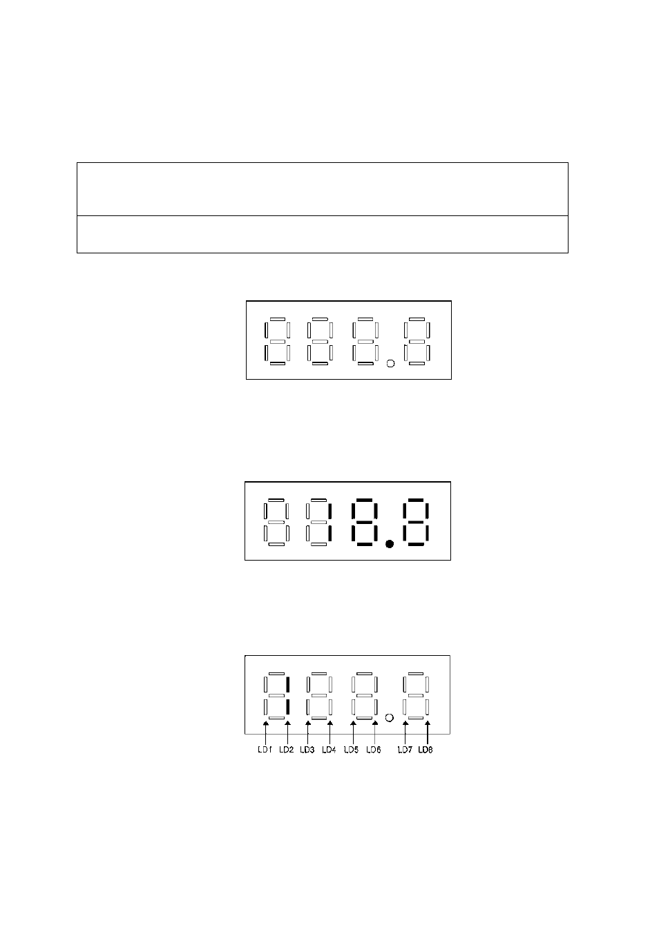
• Numerical display
Example : display at 18.8kg/cm
2
G (1.84MPa) of pressure sensor data (Item No. 56)
• Graphic display (Two LEDs aligned vertically express a flag.)
Example : At forcible powering in outdoor unit operation display