3test run – MITSUBISHI ELECTRIC P500YMF-C User Manual
Page 31
–29–
3
3
3
3
3
TEST RUN
[1] Before Test Run
(1)
Check points before test run
1
Neither refrigerant leak nor loose power source/ transmission lines should be found.
2
Confirm that the resistance between the power source terminal block and the ground exceeds 2M
Ω
by measur-
ing it with a DC 500 V megger. Do not run if it is lower than 2M
Ω
.
Note: Never apply the megger to the MAIN board. If applied, the MAIN board will be broken.
3
Confirm that the Ball valve at gas and liquid, oil balance sides are fully opened.
Note: Certainly close the cap.
4
Be sure that the crankcase heater has been powered by turning the main power source on at least 12 hours
before starting the test run. The shorter powering time causes compressor trouble.
5
If any of the power supply wires (L1, L2, L3, N,
.) are mistakenly connected, it is possible to damage the unit.
Please exercise caution.
6
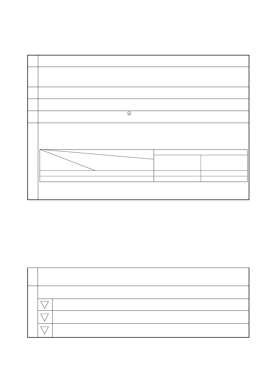
A transmission booster (RP) is required when the number of connected indoor unit models in a cooling system
exceeds the number of models specified in the chart below.
Note: The maximum number of units that can be controlled is determined by the indoor unit model, the type of
remote controller and their capabilities.
The number of indoor units and the total number of remote controllers is displayed within the parenthesis (
).
(*1) If even one unit that is higher than 200 exists in the cooling system, the maximum capacity will be “200 or
higher”.
* Please refer to the installation manual for more details.
* Before turning power on to the outdoor unit, first turn on the transmission booster. (If the outdoor unit are mistakenly
turned on first, turn on the transmission booster and then reset the outdoor unit power.)
(2)
Caution at inverter check
Because the inverter power portion in outdoor unit electrical part box have a lot of high voltage portion, be sure to follow
the instructions shown below.
During energizing power source, never touch inverter power portion because high voltage (approx. 580 V) is
applied to inverter power portion.
When checking,
Shut off main power source, and check it with tester, etc.
Allow 10 minutes after shutting off main power source.
Open the MAIN board mounting panel, and check whether voltage of both ends of electrolytic capacitor is
20 V or less.
1
2
1
2
3
200 or lower
200 or higher
Remote controller PAR-F 25MA
Prior to Ver. E
After Ver. F
16 (32)
20 (40)
16 (32)
16 (32)
(*1)
Capability of the
connected indoor units
Remote controller type
Number of connected indoor units that
can be connected without a RP.