MITSUBISHI ELECTRIC P500YMF-C User Manual
Page 80
–78–
4
“HO” indication on
the remote controller
is not lit, and the
ON/OFF switch does
not work.
1) The M-NET transmission power supply form the
outdoor unit is not supplied.
1
The original power supply of Indoor Unit is not
turned on.
2
The connector on the controller board in Indoor
Unit is removed.
Main board ----CNS1, CNVCC3
INV board----CNAC2, CNVCC1, CNL2
3
Power supply circuit defects of the outdoor unit.
(For detail, refer to Pages 127)
●
INV board defects
●
Diode stack defects
●
Prevention resistance of rush current (R1)
damage.
2) Short circuit of the M-NET transmission line
3) Error wiring of the M-NET transmission line on the
side of the outdoor unit
1
A break of the transmission line or terminal block
removal
2
Indoor Unit transmission line is wired to the
transmission line terminal block (TB7) for the
central control by mistake.
4) M-NET transmission line break on the side of Indoor
Unit (Short/ Open)
5) Loose or disconnection of wiring between the M-NET
transmission terminal block (TB 5) of Indoor Unit and
Indoor Unit controller board CN2M and disconnection of
connectors
6) Error wiring of the MA remote control
1
Short circuit of the MA remote wiring
2
A break of the MA remote control line (No.2) and
disconnection of the terminal block connection
3
Reversed wiring, cross-over in the group control
4
Wire by mistakes the MA remote control to the
terminal block (TB5) for the transmission line
5
Connect by mistakes the M-NET transmission line to
the MA remote control terminal block (TB13)
7) The unit address is not “00” as it should be with
automatic address setting.
8) The address of Indoor Unit becomes 51 or more.
9) The master and slave setting of the MA remote
control becomes the slave setting.
10)Use the M-NET remote control in spite of the
automatic address.
11)Defects for the room controller board (MA remote
communication circuits)
12)Defects for the remote controller
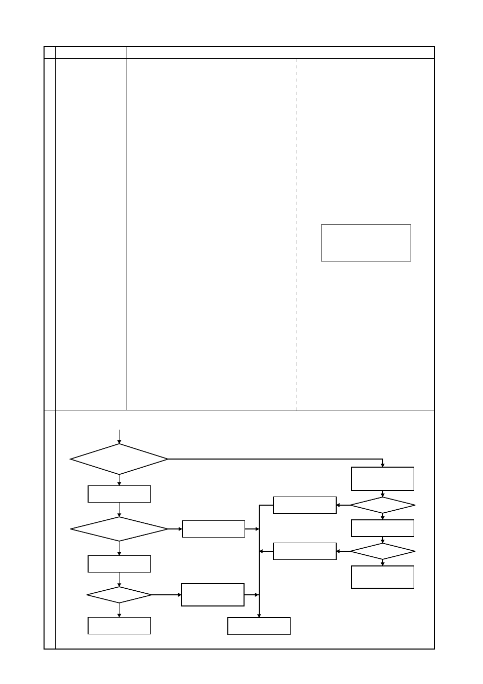
Check method and handling
Phenomena
Factors
In the case of 2), 3) and 7)
factors, indicate 7102 errors
by the self-diagnosis LED of
the outdoor unit.
NO
NO
YES
YES
NO
YES
YES
Check for 2) and 3) of
factors
Modify the defective
places
7120 error display?
Check for 11) item
Check for 4) item
19 ~ 12V?
Check the items of
5), 6), 8), 9), and 10)
Defects of the indoor
unit controller board or
MA remote control
Factors available?
Modify the defective
places
Modify the defective
places
Check for the terminal
block (TB15) voltage
for the transmission
line of the indoor unit
NO
The same
phenomena in all unit of the same
refrigerant system happen?
Self-diagnosis LED
checks
YES
NO
Factors
available?
Check for 1) item
Change the M-NET
remote control to the
MA remote control.