Pyromation Series 610 1_16 DIN User Manual
Page 95
1
/
4
-DIN,
1
/
8
-DIN &
1
/
16
- DIN Controllers & Indicators - Product Manual
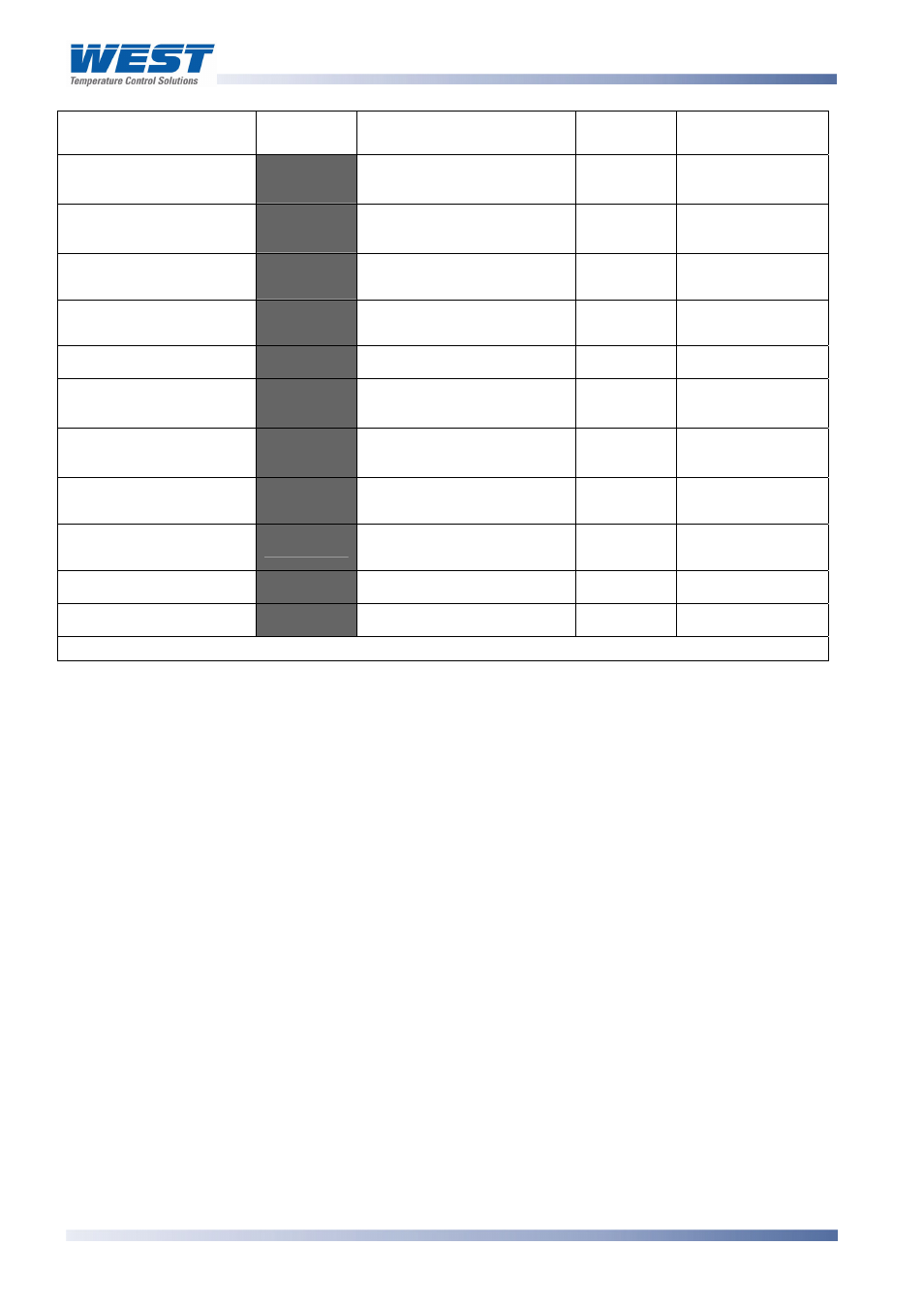
Parameter Lower
Display
Upper Display
Adjustment Range
Default
Value
When
Visible
)?
Range Min. to Range
Max.
Range
Max.
'
=
):$
Process Low Alarm 1
value*
)'
Range Min. to Range
Max.
Range
Min.
'
=
):'
='
±span from setpoint
'
=
=
'
1 LSD to full span from
setpoint.
Up to 100% of span
)?
Range Min. to Range
Max.
Range
Max.
'
=
):$
)'
Range Min. to Range
Max.
Range
Min.
'
=
):'
='
±span from setpoint
'
=
=
Band Alarm 2 value*
'
1 LSD to full span from
setpoint.
'
=
C=
$4
Up to 100% of span
Always
Set-up Lock Code
-' N
0 to 9999
Always
**First Operator mode displays follows.
Band Alarm 1 value*
'
=
C=
Alarm 1 Hysteresis*
$4
Always
Process High Alarm 2
value*
Process Low Alarm 2
value*
Note:
Alarm parameters marked * are repeated in Configuration Mode.
Note:
**Once the complete list of Set Up Mode parameters has been displayed, the first
Operator Mode display is shown without exiting from Set Up Mode.
CAUTION:
An excessively large filter time could significantly delay detection of a limit
condition. Set this value to the minimum required to remove noise from the process
variable.
Page 90
P6700, P8700& P4700 Model Group
59305, Issue 6 – March 2006