Pyromation Series 610 1_16 DIN User Manual
Page 22
1
/
4
-DIN,
1
/
8
-DIN &
1
/
16
- DIN Controllers & Indicators - Product Manual
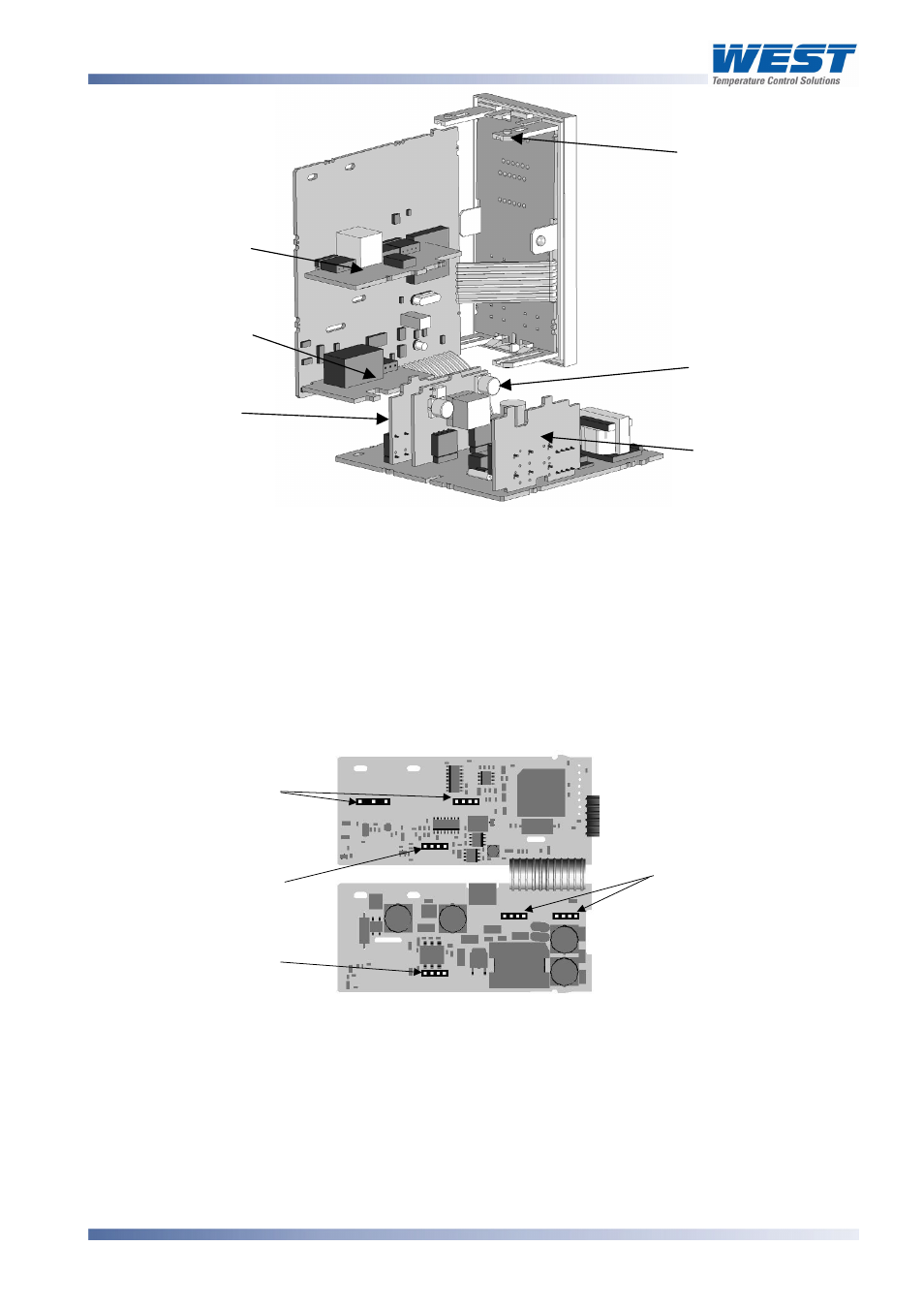
Option Slot 2
Option Slot A
Option Slot B
Option Slot 3
Option Slot 1
Mounting Struts
59305, Issue 6 – March 2006
Plug-in Options
Page 17
Figure 6. Location of Option Modules -
1
/
8
&
1
/
4
DIN Instruments
CAUTION:
Take care not to put undue stress on the ribbon cable attaching the display and
CPU boards.
2. Remove or fit the modules into the Option slots as required. The location of the connectors
is shown below. Tongues on each option module locate into a slots cut into the main
boards, opposite each of the connectors.
Option Slot 3
Connector PL4B
Option Slot 2
Connector PL4A
Option Slot A
Connectors PL5 & PL6
Option Slot 1
Connectors PL7 & PL8
Figure 7. Option Module Connectors -
1
/
16
DIN Instruments
CAUTION:
Check for correct orientation of the modules and that all pins locate correctly into
the socket