Preparing to install or remove options modules, Removing/replacing option modules – Pyromation Series 610 1_16 DIN User Manual
Page 21
1
/
4
-DIN,
1
/
8
-DIN &
1
/
16
- DIN Controllers & Indicators - Product Manual
Preparing to Install or Remove Options Modules
CAUTION:
Before removing the instrument from it’s housing, ensure that all power has been
removed from the rear terminals.
1. Remove the instrument from its housing by gripping the side edges of the front panel
(there is a finger grip on each edge) and pull the instrument forwards. This will release the
instrument from the rear connectors in the housing and will give access to the PCBs.
2. Take note of the orientation of the instrument for subsequent replacement into the
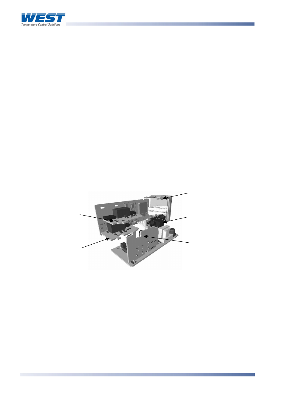
housing. The positions of the main and option PCBs in the instrument are shown below.
Removing/Replacing Option Modules
With the instrument removed from its housing:
1. To remove or replace modules into Option Slots 1,A or B, it is necessary to gently
separate the CPU and PSU PCBs. This is achieved by detaching the main boards (PSU
and CPU) from the front moulding by lifting first the upper and then lower mounting struts
as shown. This frees the boards from the front. If only Option slots 2 or 3 are to be
changed, this stage is not required as these slots are accessible without separating the
main boards from the front.
Option Slot 2
Option Slot 3
Option Slot A
Option Slot 1
Mounting Struts
Figure 5. Location of Option Modules -
1
/
16
DIN Instruments
CAUTION:
Take care not to put undue stress on the ribbon cable attaching the display and
CPU boards.
Page 16
Plug-in Options
59305, Issue 6 – March 2006