Pyromation Series 610 1_16 DIN User Manual
Page 100
1
/
4
-DIN,
1
/
8
-DIN &
1
/
16
- DIN Controllers & Indicators - Product Manual
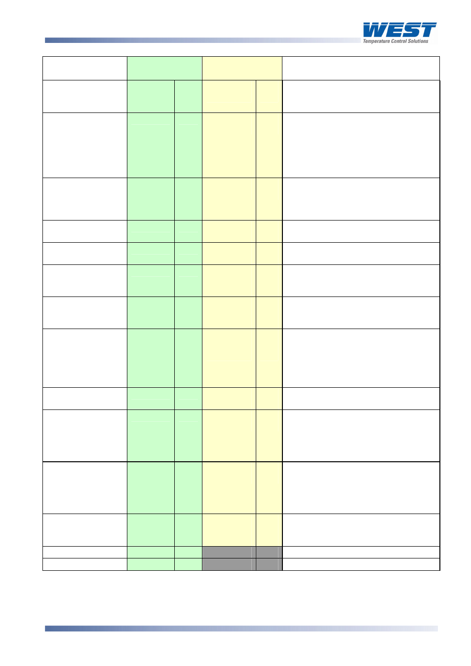
Parameter
Modbus
Parameter No.
ASCII Ident &
Message Types
Notes
Deviation
4
RO
V
Type 2
RO
Difference between Process Variable
and Limit Setpoint (value = PV-Limit
SP)
5
R/W
RO
Accumulated time of Limit SP exceed
conditions since this parameter was
last reset.
Modbus: Write any value to reset
ASCII: See Controller Command
00170 for reset
R/W
A band on the “safe” side of the Limit
SP. Adjustable 0 to 100% of span. A
latched limit relay cannot be reset until
the process passes through this band
R/W
Alarm 1 active at this level
R/W
Alarm 2 active at this level
H
Type 2
Type 3/4
RO
R/W
R/W
G
Type 2
Type 3/4
R/W
Q
Type 2
Type 3/4
3 = x.xxx
R/W
0 to 100 seconds
R/W
[
Type 2, 3/4
R/W
Maximum scale value for retransmit
output, 1999 to 9999. This parameter
applies to the first re-transmit output
fitted (see also Modbus parameters
2224, 2225, 2234 & 2235).
Re-transmit Output
Minimum
R/W
Minimum scale value for retransmit
output, 1999 to 9999. This parameter
applies to the first re-transmit output
fitted (see also Modbus parameters
2224, 2225, 2234 & 2235).
v
Type 2
Type 3/4
RO
R/W
32
R/W
0 to 100% of span
33
R/W
0 to 100% of span
T
Type 2
Limit Hysteresis
6
R/W
F
Type 2, 3/4
Alarm 1 Value
7
R/W
C
Type 2, 3/4
Alarm 2 Value
8
R/W
E
Type 2, 3/4
Scale Range
Lower Limit
9
R/W
Lower limit of scaled input range
Scale Range
Upper Limit
10
RO
R/W
Upper limit of scaled input range
Decimal Point
Position
11
RO
R/W
Read only if not Linear Input.
0 = xxxx
1 = xxx.x
2 = xx.xx
12
R/W
m
Type 2, 3/4
Re-transmit output
Maximum
13
14
R/W
\
Type 2, 3/4
Process Value
Offset
26
R/W
Modified PV = Actual PV + PV Offset.
Limited by Scale Range Max. and
Scale Range Min.
Alarm 1 Hysteresis
Alarm 2 Hysteresis
59305, Issue 6 – March 2006
P6700, P8700 & P4700 Model Group
Page 95