Pyromation Series 610 1_16 DIN User Manual
Page 76
1
/
4
-DIN,
1
/
8
-DIN &
1
/
16
- DIN Controllers & Indicators - Product Manual
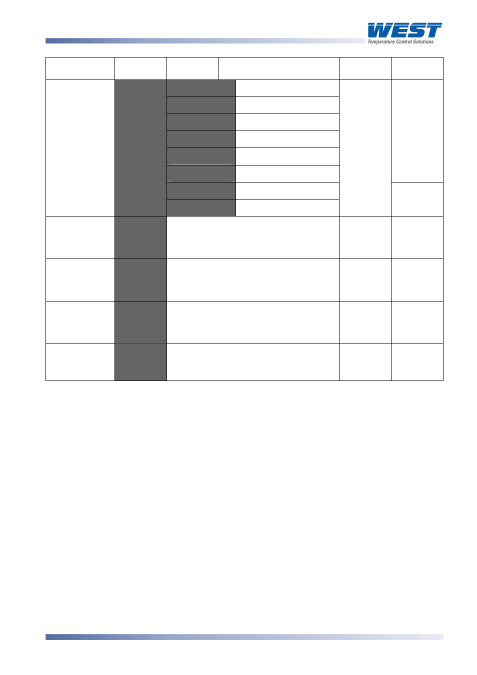
Parameter Lower
Display
Upper
Display
Description Default
Value
When
Visible
:
0 to 20mA DC input
:
4 to 20mA DC input
:
0 to 10V DC input
:
2 to 10V DC input
:
0 to 5V DC input
:
1 to 5V DC input
@C
or
@C
=
+-)
0 to 100mV DC input
+C)
) /
Potentiometer (
≥2KΩ)
:
(
or
) /
if
)
=
)C
)
@C
=
+-)
+-)1
to
RSP value to be used when RSP input is
at maximum.
Range
max
)
or
)
=
+-)
+-)'
to
RSP value to be used when RSP input is
at minimum.
Range min
)
or
)
=
+-)
+-)
Offset applied to RSP value. Constrained
within Scale Range Upper Limit and
Scale Range Lower Limit.
)
or
)
=
+-)
Configura-
tion Mode Lock
Code
3' N
to
Always
*Note:
Alarm parameters marked * are repeated in Setup Mode.
**Note:
This controller uses Three-Point Stepping control. This requires two identical outputs (2
Relays, 2 Triacs, 2 SSR Drivers or 1 Dual Relay) to be configured for the )( (Valve
Open) & 3'- (Valve Close) functions.
***Note:
If
=#
or
=#
=
=-
the remote setpoint input feature is disabled. The instrument
uses the two internal setpoints (SP1 & SP2) instead.
If
=#
and
=#
are set to the same value, the status of digital input 2 will take
precedence over digital input 1.
=#
cannot be set for Remote/Local Setpoint Selection if (
=+-
) if Auxiliary Input B is
used for Valve Position Indication.
59305, Issue 6 – March 2006
P6170, P8170 & P4170 Model Group
Page 71