Pyromation Series 610 1_16 DIN User Manual
Page 91
1
/
4
-DIN,
1
/
8
-DIN &
1
/
16
- DIN Controllers & Indicators - Product Manual
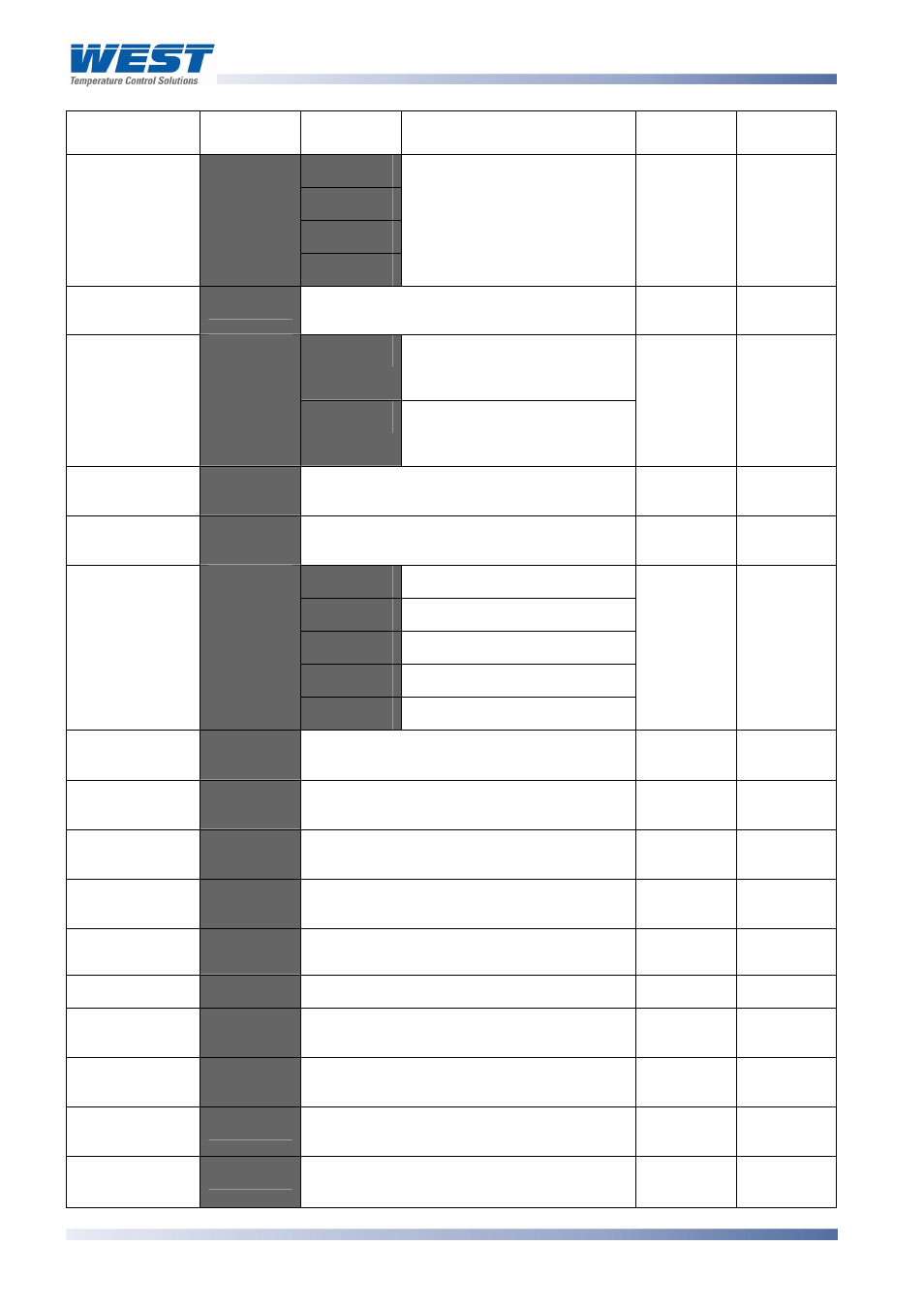
Parameter Lower
Display
Upper
Display
Description Default
Value
When
Visible
Decimal point
position
=) -
Decimal point position in
non-temperature ranges.
0 = XXXX
1 = XXX.X
2 = XX.XX
3 = X.XXX
%C@.
=
mV, V or
mA
""-
±Span of controller (see
CAUTION
note
at end of section)
Always
$
High Limit. Limit relay is
energised when process
“safe” (PV < Limit Setpoint)
Limit Action
3.*'
'
Low Limit. Limit relay is
energised when process
“safe” (PV > Limit Setpoint)
$
Always
-)1'
Current Setpoint value to Scale Range
Maximum
Range
Max.
Always
-)''
Scale Range Minimum to current Setpoint
value
Range
Min
Always
):$
Process High Alarm
):'
Process Low Alarm
=
Deviation Alarm
C=
Band Alarm
Alarm 1Type
'
C C
No alarm
):$
Always
)?
Range Min. to Range Max.
Range
Max.
'=
):$
Process Low
Alarm 1 value*
)'
Range Min. to Range Max
Range
Min.
'=
):'
='
±span from setpoint
'=
=
'
1 LSD to full span from setpoint.
'=
C=
$4
1 LSD to 100% of span (in display units)
on “safe” side of alarm point.
Always
Alarm 2 Type
'
As for alarm 1 type
):'
Always
)?
Range Min. to Range Max.
Range
Max.
'=
):$
)'
Range
Min.
'=
):'
='
±span from setpoint.
'=
=
'
1 LSD to full span from setpoint.
'
=
C=
Range Min. to Range Max.
Deviation
Alarm 2 Value*
Page 86
P6700, P8700& P4700 Model Group
59305, Issue 6 – March 2006