Option slot 2 - relay output module, Option slot 2 - ssr driver output module, Option slot 2 - triac output module – Pyromation Series 610 1_16 DIN User Manual
Page 34: Po2-c50, Ssr driver, Po2-c80, Triac
1
/
4
-DIN,
1
/
8
-DIN &
1
/
16
- DIN Controllers & Indicators - Product Manual
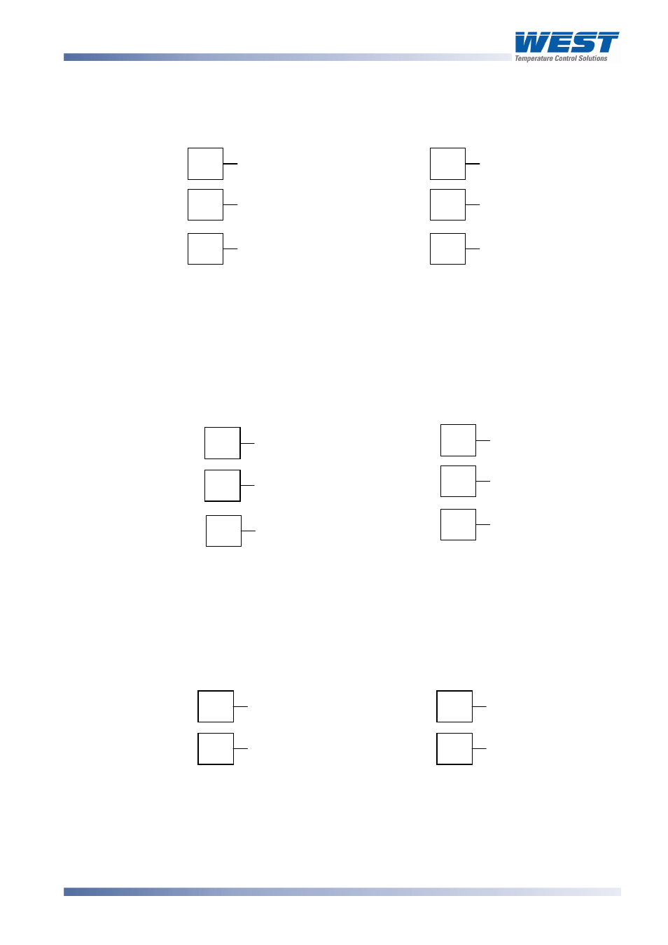
Option Slot 2 - Relay Output Module
If option slot 2 is fitted with a relay output module, make connections as illustrated. The relay
contacts are rated at 2 amps resistive, 240 VAC (120V max for direct Valve Motor control).
22
23
N/C
COM
24
N/O
13
14
N/O
COM
15
N/C
1
/
16
DIN
1
/
4
DIN &
1
/
8
DIN
Figure 22.
Option Slot 2 - Relay Module
Option Slot 2 - SSR Driver Output Module
If option slot 2 is fitted with an SSR driver output module, make connections as illustrated.
The solid-state relay driver is a 0-10V DC signal, load impedance must be no less than 500
ohms. SSR driver outputs are not isolated from the signal input or other SSR driver outputs.
22
23
24
14
15
_
_
+
13
+
1
/
16
DIN
1
/
4
DIN &
1
/
8
DIN
Figure 23.
Option Slot 2 - SSR Driver Module
Option Slot 2 - Triac Output Module
If option slot 2 is fitted with a Triac output module, make connections as shown. This output
is rated at 0.01 to 1 amp @ 280V AC 50/60Hz. (140V max for direct Valve Motor control).
13
14
∼
23
24
∼
1
/
16
DIN
1
/
4
DIN &
1
/
8
DIN
Figure 24.
Option Slot 2 - Triac Module
WARNING:
THIS MODULE MUST NOT BE FITTED INTO OPTION SLOT 3.
59305, Issue 6 – March 2006
Connections
Page 29