Pyromation Series 610 1_16 DIN User Manual
Page 121
1
/
4
-DIN,
1
/
8
-DIN &
1
/
16
- DIN Controllers & Indicators - Product Manual
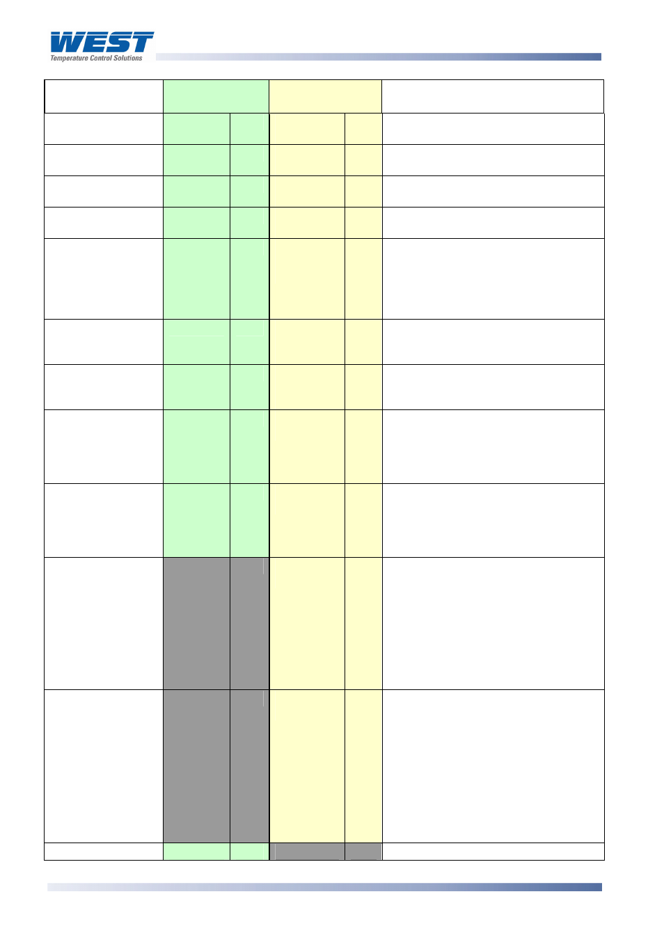
Parameter
ASCII Ident &
Message Types
Notes
Modbus
Parameter No.
Alarm 1 Hysteresis
10
R/W
D
Type 2, 3/4
R/W
0 to 100% of span
Alarm 2 Hysteresis
11
R/W
F
Type 2, 3/4
R/W
0 to 100% of span
Alarm 3 Hysteresis
12
R/W
O
Type 2, 3/4
R/W
0 to 100% of span
Input Filter Time
Constant
13
R/W
m
Type 2, 3/4
R/W
0 to 100 seconds
Decimal Point
Position
14
R/W
Q
Type 2
Type 3/4
RO
R/W
0 = xxxx
1 = xxx.x
2 = xx.xx
3 = x.xxx
Read only if not Linear Input.
Scale Range
Lower Limit
15
R/W
H
Type 2
Type 3/4
RO
R/W
Lower limit of scaled input range
Scale Range
Upper Limit
16
R/W
G
Type 2
Type 3/4
RO
R/W
Upper limit of scaled input range
Re-transmit Output
Maximum
18
R/W
[
Type 2, 3/4
R/W
Maximum scale value for retransmit
output, 1999 to 9999. This parameter
applies to the first re-transmit output
fitted (see also Modbus parameters
2214, 2224 & 2234).
Re-transmit Output
Minimum
17
R/W
\
Type 2, 3/4
R/W
Minimum scale value for retransmit
output, 1999 to 9999. This parameter
applies to the first re-transmit output
fitted (see also Modbus parameters
2215, 2225 & 2235).
Scan Table
]
Type 2
R
Reads back main process values.
Response is: L{N}25aaaaabbbbb
cccccdddddeeeeeA* where:
aaaaa = Process Variable value
bbbbb = Stored Maximum PV value
ccccc = Stored Minimum PV value
ddddd = Stored Alarm 1 Elapsed Time
eeeee = Instrument Status (see
.
above)
Instrument
commands
Z
Type 3/4
WO
Only Type 3 / 4 ASCII messages are
allowed with this parameter. The
{DATA} field must be one of four 5-
digit numbers. The commands
corresponding to the {DATA} field
value are:
00150 = Unlatch Alarm 1 relay
00160 = Reset Stored Max PV
00170 = Reset Stored Min PV
00180 = Reset Alm1 Elapsed Time
Equipment ID
122
RO
The four digit model number 8010
Page 116
P6010 & P8010 Model Group
59305, Issue 6 – March 2006